71 / 155
Service Manual Mitsubishi L-Series diesel engines
Version 08/2004
PISTON AND CONNECTION ROD
ENGLISH
ENGINE MAIN PARTS
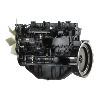
2. Installation of piston rings
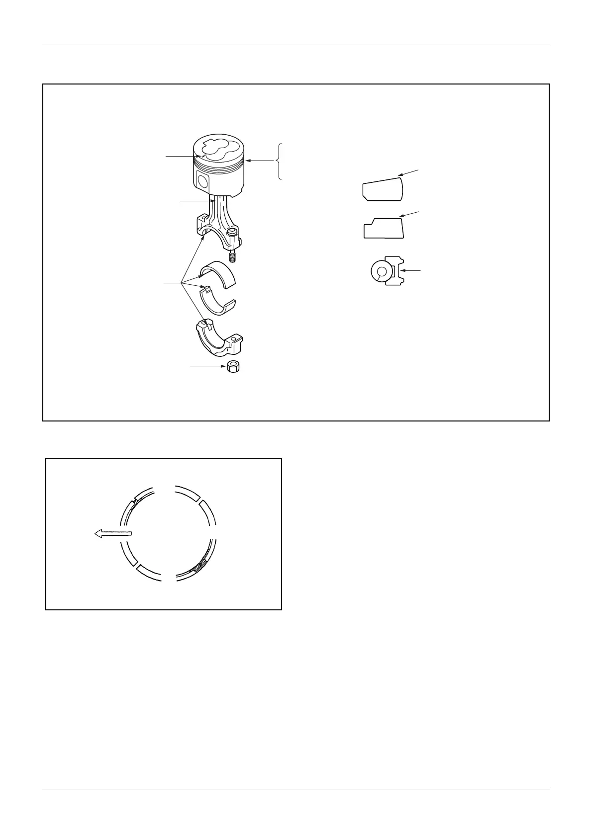
3. Set the piston ring gaps to the proper positions as
shown at right. Apply oil to the rings and cylinder
wall.
4. Using a piston-ring compressor to compress the
rings into the grooves, push the piston-and-
connecting rod assembly down into the cylinder.
Be careful not to break the rings by knocking the
head of piston excessively. Note that the front
marks on the piston and connecting rod are in
direction of the engine front.
FRONT mark
Rod front mark
Align lugs accurately
each other.
Tightening torque:
31.4 to 34.3 N²m
(3.2 to 3.5 kgf²m)
[23.15 to 25.32 lbf²ft]
Ring set positions:
No. 1 ring,
No. 2 ring,
oil ring
“T” mark and OS size mark
“T” mark and OS size mark
OS size identification paint
Color of discrimination:
STD = Without color
0.25 = White
0.50 = Blue
Figure 74 Reassembly of piston rings and
connecting rod cap
Figure 75 Proper arrangement of ring gaps
Oil ring gap
No. 1 ring gap
Coil expanded
joint of oil ring
Front
No. 2 ring gap
 Loading...