8 - 2 8 - 2
MELSEC-Q
8 TROUBLESHOOTING
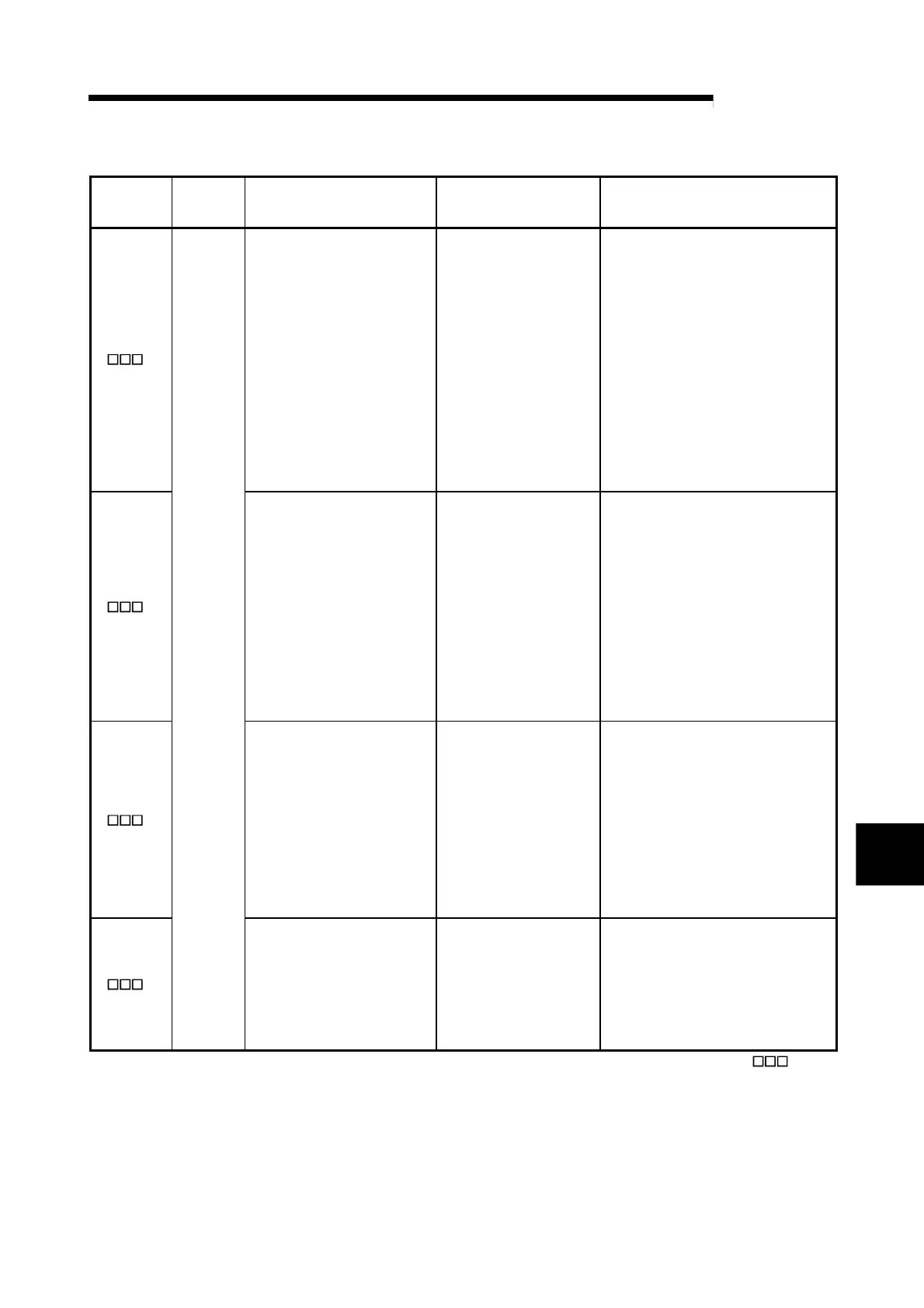
(2) Error Code List
Error code
(hexadecim
al)
*1
Error type Cause Error-time operation Corrective action
• Write to the area write-enabled
in the setting mode only was
performed in the operation
mode.
• Any of the following error codes
occurred during setting mode;
however, the mode is changed
to operation mode without
resetting the error.
3H
• Write data error to input range
(error code: 0204
H, 0404H)
• Write error to alert mode
setting (error code: 0C04
H,
0C14
H, 0C24H, 0C34H,
0D04
H, 0D14H, 0D24H,
0D34
H)
• The written data is held as
is.
• If data are written to
multiple write areas, the
smallest buffer memory
address among the ones
where data were
mistakenly written is stored
by priority.
• Make error rest in the following
procedure:
1) Choose the setting mode.
2) Set a correct value.
3) Make error reset.
• When changing from the operation mode
to the setting mode, make sure that the
PID continuation flag (buffer memory
address: 169) is 0 (STOP), and turn off
the setting/operation mode command
(Yn1).
4H
• Data outside the setting range
was written.
• The written data is held as
is.
• When write area setting is
over the upper and lower
limit values, the upper and
lower limit values are used
to exercise the control.
• If multiple data outside the
setting range were written,
the smallest buffer memory
address among the ones
where data were
mistakenly written is stored
by priority.
• Set data within the range.
5H
• The setting of the upper/lower
output limiter or upper/lower
setting limiter is illegal.
• The written data is held as
is.
• The upper and lower limit
values that may be set are
used to exercise control.
• If data are written to
multiple limiter setting area,
the smallest buffer memory
address among the ones
where data were
mistakenly written is stored
by priority.
• Make setting so that the upper limit value
is greater than the lower limit value.
6H
Write data
error
• The set value was changed
during default setting
registration.
• The written data is ignored.
• Any set value cannot be
changed until error reset is
made.
• If another write error
occurs, error code (the
buffer memory address: 0)
data does not change.
• After making error reset command (Yn2:
ON), change the set value.
*1 The buffer memory address occurring write data error is displayed at " " in
hexadecimal.
Example) "0234
H" expresses that data out of the range are written to proportional
band (P) setting (buffer memory address: 35 (23
H)).
8

 Loading...


