3 - 28 3 - 28
MELSEC-Q
3 SPECIFICATIONS
(c) Zone PID data
The zone PID data divides input range into 8 zones by zone upper limit setting,
and then sets the PID constants and control response parameters used for each
zone.
Zone dividing is performed by the upper limit setting (refer to the table on the next
page for buffer memory) of zone 1 to 8.
Selecting the PID constants and control response parameters used in each
segment is performed by the zone PID data No. (refer to the table on the previous
page for buffer memory).
There are following three types for selecting the method.
1) When selecting optionally the PID constants and control response parameters
Set 1 to 8 to the zone PID data No. for each segment.
The Q62HLC performs the control using the PID constants and control
response parameter of zone 1 to 8.
2) When selecting automatically the PID constants and control response
parameters
The zone PID data No. is set to 0.
The Q62HLC performs the control after automatically selecting the zone
including the set value of segment in execution.
If the characteristics of control target differ depending on the zone, the control
performance can be improved being compared with the case where a single
PID constant is used for controlling.
3) When controlling with the PID constants and control response parameters
Zone 1 upper limit is set as input range upper limit, and 0 is set to zone PID
data No. of each segment.
The Q62HLC performs the control using the PID constants and control
response parameter of zone 1.
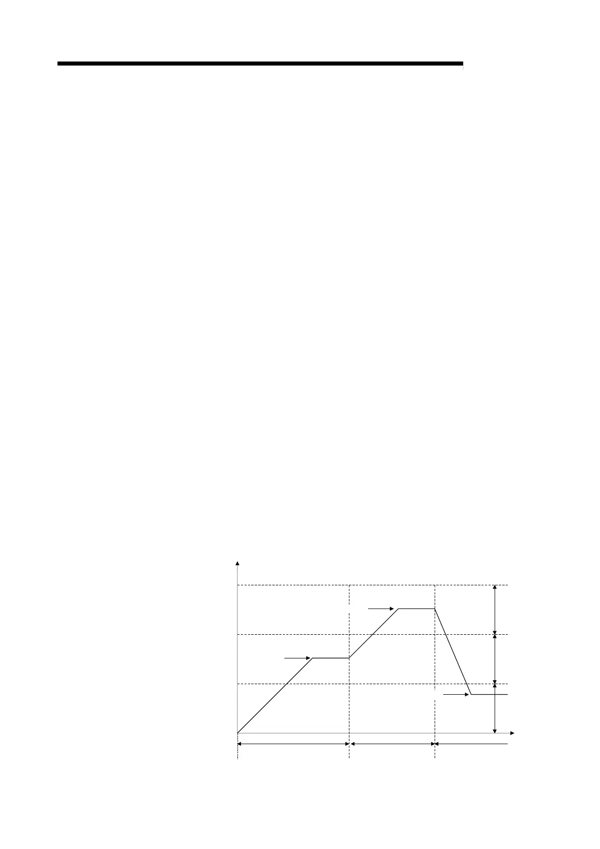
Example) When dividing the input range into 3 zones and when setting 2 for the
PID data setting of the execution zone (For buffer memory addresses,
check the following table) in the segment 1 and 2, setting 3 for the PID
data setting of the execution zone in the segment 3 and 4, setting 1 for
the PID data setting of the execution zone in the segment 5 and 6
Set value
Time
Zone 3
Zone 2
Zone 1
Set value B
Set value C
Set value A
Zone 3 upper limit
Zone 2 upper limit
Zone 1 upper limit
(Input range upper limit)
It is controlled by the PID
constant of zone 2.
It is controlled by
the PID constant
of zone 3.
It is controlled by
the PID constant
of zone 1.

 Loading...


