3
1 Overview
No. 99MBC122A
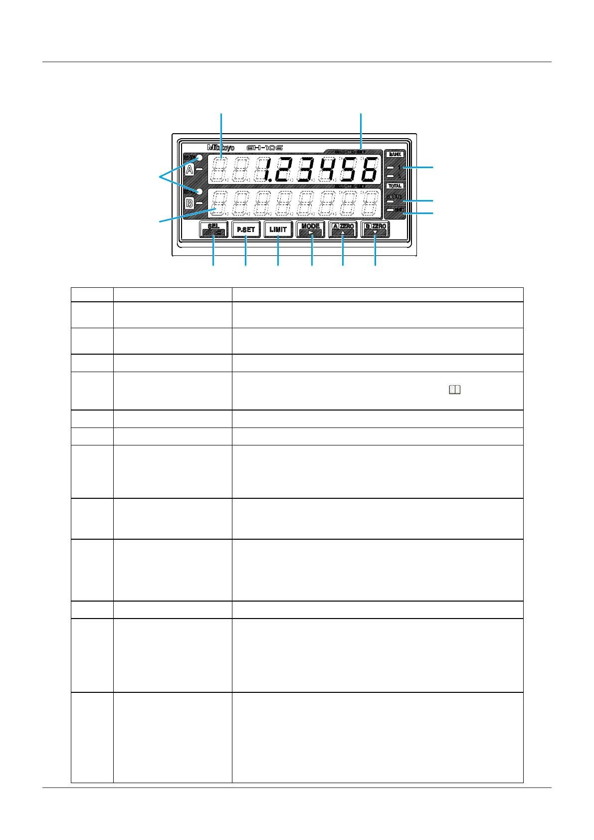
1.2.2 Counter Front
①
⑧ ⑨ ⑩ ⑪ ⑫ ⑬
③
④
⑤
②
⑥
⑦
No. Name Description
①
Ach (upper display) Displays the counter value from INPUT A (gage input connec-
tor).
②
Bch (lower display) Displays the peak, speed, or other value from INPUT A (gage
input connector) if assigned (nothing by factory default).
③
Peak indicator Indicates the Peak-mode type.
④
BANK indicator Indicates the currently selected BANK number (xed to BANK1
by factory default). For details about BANK, see "4.2 Switch-
ing the Displayed BANK" (page 31).
⑤
GO/NG indicator Indicates the result of the tolerance judgment.
⑥
Total judgment indicator Indicates the result of the total tolerance judgment by color.
⑦
UNIT indicator y Blinks while a HOLD signal is being input when the I/O con-
nector is connected.
y Lights when an E unit has been selected for the correspond-
ing parameter.
⑧
[SEL] key y Switches between Ach (upper display) and Bch (lower dis-
play) (xed to BANK1 by factory default).
y Cancels an error.
⑨
[P.SET] key Sets a Preset value.
Tips
When setting a parameter, this sets the parameter number.
⑩
[LIMIT] key Sets the tolerance value.
⑪
[MODE] key Sets Peak mode.
Tips
When setting the tolerance, preset, or optional constant value, this
moves the current input digit from left to right.
⑫
[A_ZERO] key Sets the current value in Ach (upper display) to 0.
Tips
• When setting a parameter, this advances the set value.
• When setting the tolerance, preset, or optional constant value, this
increases the value of the selected digit.
 Loading...