35
4 Basic Operations
No. 99MBC122A
8
Press [LIMIT].
» The tolerance value S4 is determined, and the counter returns to the counter value status.
Tips
An error will occur unless S1 ≤ S4. Press [SEL] to re-enter from S1.
4.6.2 5-Step Tolerance Value Setting (5-Step Tolerance Zone Se-
lection)
With S1–S4 set as the tolerance values, the 5-step tolerance judgment will be performed as follows:
GO/NG indicator I/O output
Measured value < S1 Amber indicator on AL1/BL1
S1 ≦ Measured value < S2
Amber indicator blinks AL2/BL2
S2 ≦ Measured value ≦ S3
Green indicator on AL3/BL3
S3 < Measured value ≦ S4
Red indicator blinks AL4/BL4
S4 < Measured value Red indicator on AL5/BL5
This section explains how to set the 5-step tolerance value.
1
Press [SEL] to select one of the operation channels from Ach (upper display) and Bch (lower display).
2
Press [LIMIT].
» The GO/NG indicator lights in amber. (Tolerance value S1 is selected.)
» The decimal point blinks, and the previous tolerance value appears.
Tips
Tolerance values are set in the order S1, S2, S3, S4. The GO/NG indicator displays as follows: (The tolerance
value to be set is selected.)
Tolerance value
GO/NG indicator
S1 Amber indicator on
S2 Amber indicator blinks
S3 Red indicator blinks
S4 Red indicator on
3
Press [MODE].
» The input digit will shift to the right.
4
Press [A_ZERO] or [B_ZERO].
» The tolerance value will be modied.
Tips
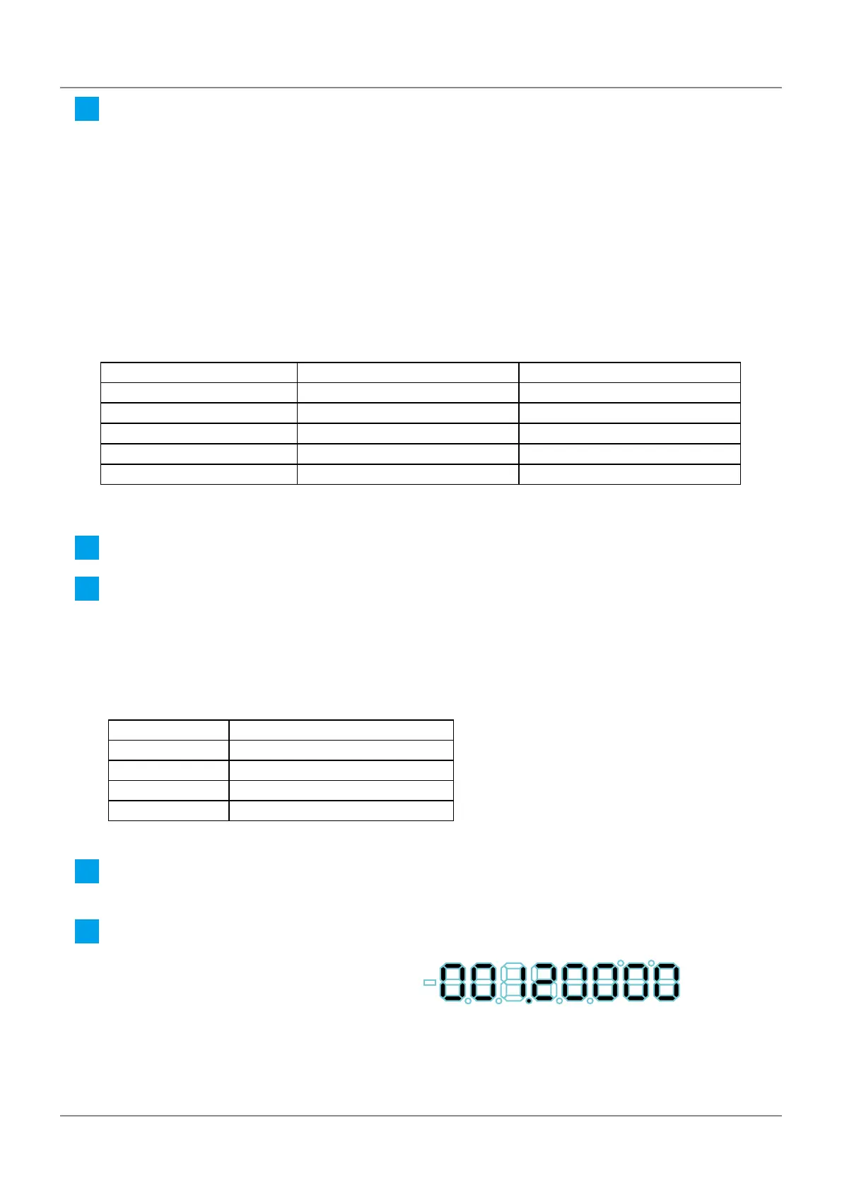
For the most signicant digit, select the sign ± also (0
⇒
...
⇒
9
⇒
-0
⇒
...
⇒
-9
⇒
0).
 Loading...