8
2 Setup
No. 99MBC122A
2.2
Mounting
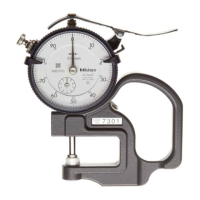
2.2.1 Gage Head
Contact point replacement procedure
Various optional special contact points and extender rods for the dial indicators are available.
A sharp tipped contact point may cause injury.Be extremely careful in handling when replacing and using it.
When replacing the contact point, use the supplied spanner and do not apply a strong turning or lateral force to
the spindle. Doing so may cause damage or malfunction of the spindle.
Tips
• A new contact point may change the external dimensions and measuring force, and the measuring direction
may be limited.
• Depending on the shape, use of a contact point other than those supplied may cause errors to accumulate.
1
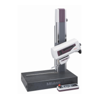
Remove the gage head from the stand.
2
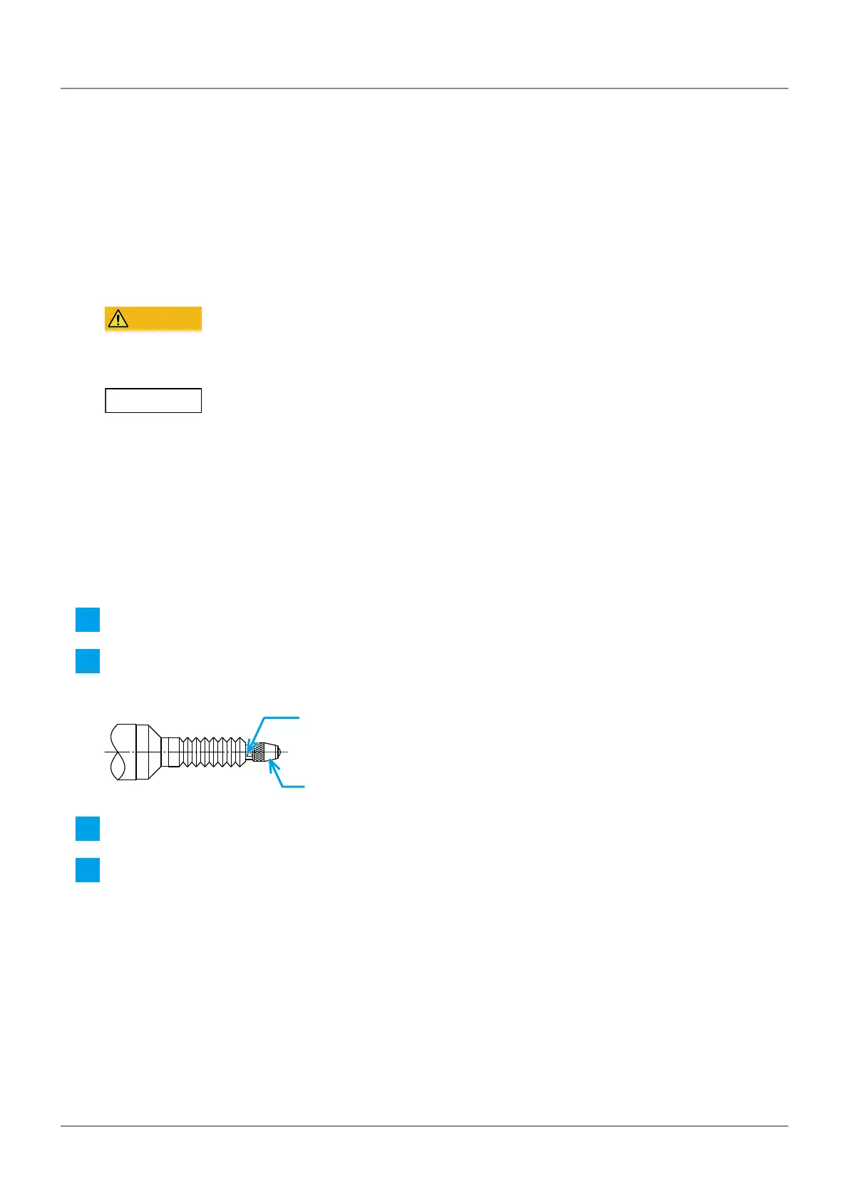
Set the supplied spanner to the spanner catch at the tip of the spindle (see the gure below) to lock the
rotation of the spindle.
Spanner catch
Contact point
3
Use pliers over a soft cloth to pinch the contact point to protect the contact point and remove it.
4
Attach the contact point in reverse order of removal.
Tips
• The recommended tightening torque is 0.5 N・m.
• After attaching the contact point, make sure that it is not loose.
• For the contact points of the dial indicator, see the General Catalog.
 Loading...