34
4 Basic Operations
No. 99MBC122A
4.6
Tolerance Value Setting
The Tolerance Judgment function supports the 3- and 5-step tolerance judgments.
Tips
• Set the set value of Parameter Number 20 to 0 (3-step tolerance) or 1 (5-step tolerance) in advance.
• When Parameter Number 20 is set to 2 (BCD output), the number of the tolerance steps remains unchanged
as just before the BCD output is set.
4.6.1 3-Step Tolerance Value Setting (3-Step Tolerance Zone Se-
lection)
With S1 and S4 set as the tolerance values, the 3-step tolerance judgment will be performed as fol-
lows:
GO/NG indicator I/O output
Measured value < S1 Amber indicator on AL1 / BL1
S1 ≦ Measured value ≦ S4
Green indicator on AL3 / BL3
S4 < Measured value Red indicator on AL5 / BL5
This section explains how to set the 3-step tolerance value.
1
Press [SEL] to select one of the operation channels from Ach (upper display) and Bch (lower display).
2
Press [LIMIT].
» The GO/NG indicator lights in amber. (Tolerance value S1 is selected.)
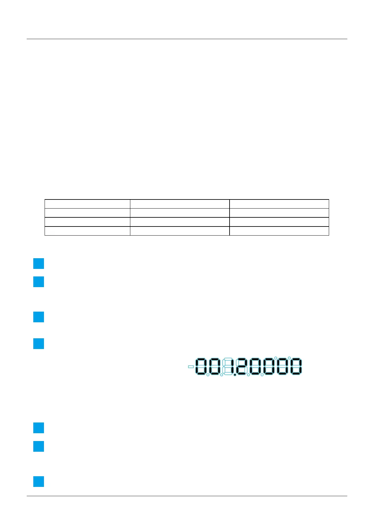
» The decimal point blinks, and the previous tolerance value appears.
3
Press [MODE].
» The input digit will shift to the right.
4
Press [A_ZERO] or [B_ZERO].
» The tolerance value will be modied.
Tips
For the most signicant digit, select the sign ± also (0
⇒
...
⇒
9
⇒
-0
⇒
...
⇒
-9
⇒
0).
5
Repeat steps 3 and 4 until the desired tolerance value is set.
6
Press [LIMIT].
» Tolerance value S1 will be applied.
» The GO/NG indicator lights in red. (Tolerance value S4 is selected.)
7
Set the tolerance value S4 using the same procedure as steps 3–5.
 Loading...