43
5 External Input/Output Function
No. 99MBC122A
5.3.2 Communication Commands
This section explains the command format from a PC or PLC, output from the counter, and operation
details.
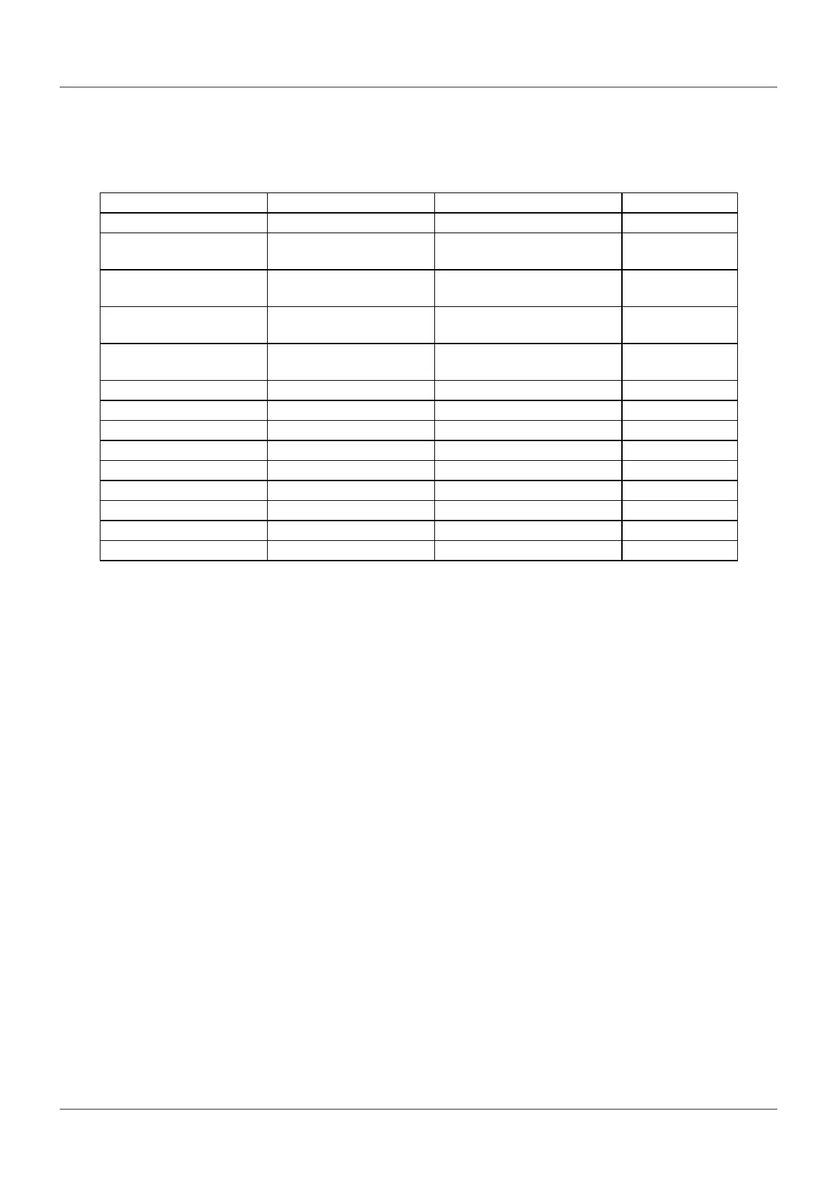
Command format Corresponding output Operation details Notes
GA**CRLF G#**, +01234.567CRLF Outputs "Display value" See *1
CN**CRLF CH**CRLF
Switches the display to "Cur-
rent value"
See *2
CX**CRLF CH**CRLF
Switches the display to "Maxi-
mum value"
See *2
CM**CRLF CH**CRLF
Switches the display to "Mini-
mum value"
See *2
CW**CRLF CH**CRLF Switches the display to
"TIR"
See *2
CR**CRLF CH**CRLF Zero setting
C L* *C R L F CH**CRLF Clears the peak value
CP**,+01234567CRLF CH**CRLF Inputs the preset value See *3
CD**,+01234567CRLF CH**CRLF Inputs tolerance value S1 See *4
CE**,+01234567CRLF CH**CRLF Inputs tolerance value S2 See *4
CF**,+01234567CRLF CH**CRLF Inputs tolerance value S3 See *4
CG**,+01234567CRLF CH**CRLF Inputs tolerance value S4 See *4
CS**CRLF CH**CRLF Clear error
CK**CRLF CH**,%CRLF Checks the HOLD status See *5
*1 "**" denotes an RS-232C Linear Gage channel number (01 to 99) ("00" means all channels). Channels 01 to
04 correspond to CEL1 to CEL4, respectively.
A "#" after "G" in the output data denotes the type of data (N: Current value, X: Maximum value, M: Minimum
value, W: TIR).
*2 If Peak mode is switched using an RS command, data will not be backed up in the internal memory.
*3 For the preset value and tolerance value, enter a value consisting of a +/- sign and an 8-digit of numeric value
without a decimal point.
*4 Perform the tolerance setting in the order CD command→CG command for 3-step tolerance, and in the
order CD command→CE command→CF command→CG command for 5-step tolerance.
An error will be output in the following cases. In this case, redo the settings from the CD command.
• If the order of the tolerance values is incorrect
• If the step count and sent data are dierent
• If incorrect data is sent
*5 The response output from the CK command ("%") shows the HOLD status.
%=0: Normal status/1: HOLD status
If Parameter Number 28 is set to 1 (channel synchronization), all counters connected via RS LINK will switch
to the HOLD state when a CK command is sent.
The HOLD state will be canceled by reading out data with the GA command.
The CK command is valid only with channel number 1 (CK01CRLF).
 Loading...