51
5 External Input/Output Function
No. 99MBC122A
Example of output data (when the Parameter Number 21 is set to "0")
D1 D2 D3 D4 D5 D6 D7 D8
A_bit0 H L L H L H L H
A_bit1 L L H L L H H L
A_bit2 L L H H H L L L
A_bit3 L L L L L L L L
A_SIGN H H L L (Not used) (Not used) (Not used) (Not used)
↓
+12345601/BANK2 Ach/Current value
Tips
• To enable this function, select set value 2 (BCD output) of Parameter Number 20 (Tolerance/BCD output
mode switching).
• It is possible to invert the data output logic by setting Parameter Number 21 (logic selection) to 1 (H).
• For details on the timing chart, see "5.5.4 Timing Chart" (page 52).
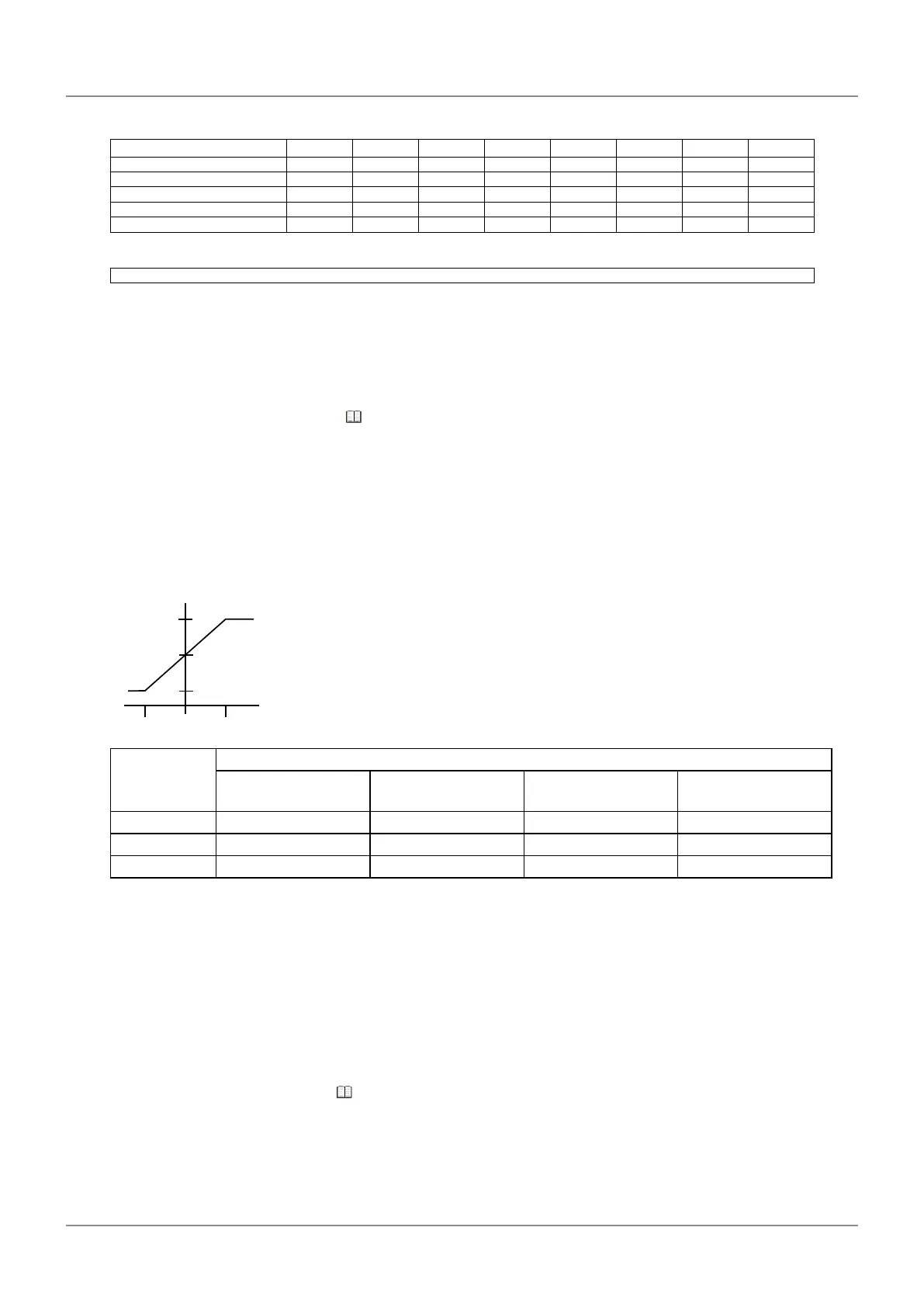
Analog output
Movement of the spindle of the gage head can be monitored as linear voltage by measuring the volt-
age between terminals with a pen recorder or oscilloscope.
Ach (upper display): Pin numbers 22–24
Bch (lower display): Pin numbers 23–24
1.0 V
4.0 V
2.5 V
0 1999-1999
Output voltage = 2.5 V + counter value × voltage resolution (0.75 mV)
(full-scale: 1.0 V–4.0 V)
Response speed: 10 Hz (update time: 5 ms)
Accuracy : ±1 % (1.0 V–4.0 V) (accuracy is rated at full-scale 4 V)
Load resistance 300 kΩ or more
Parameter
No. 30
Measurement range [mm] (range resolution [mm])
10 µm resolution
setting
1 µm resolution
setting
0.1 µm resolution
setting
0.01 µm resolution
setting
0 ±19.99 (0.01) ±1.999 (0.001) ±0.1999 (0.0001) ±0.01999 (0.00001)
1 ±199.90 (0.1) ±19.990 (0.01) ±1.9990 (0.001) ±0.19990 (0.0001)
2 ±1999.00 (1) ±199.90 0 (0.1) ±19.9900 (0.01) ±1.99900 (0.001)
5.5.3 Input Function
With an external signal input, you can switch the BANK, switch Peak mode, activate the Preset func-
tion, clear the peak value, set the memory, and clear the memory.You can also activate a HOLD on
the counter values of Ach (upper display) and Bch (lower display) either separately or simultaneously.
Tips
For details on the timing chart, see "5.5.4 Timing Chart" (page 52).
 Loading...