52
5 External Input/Output Function
No. 99MBC122A
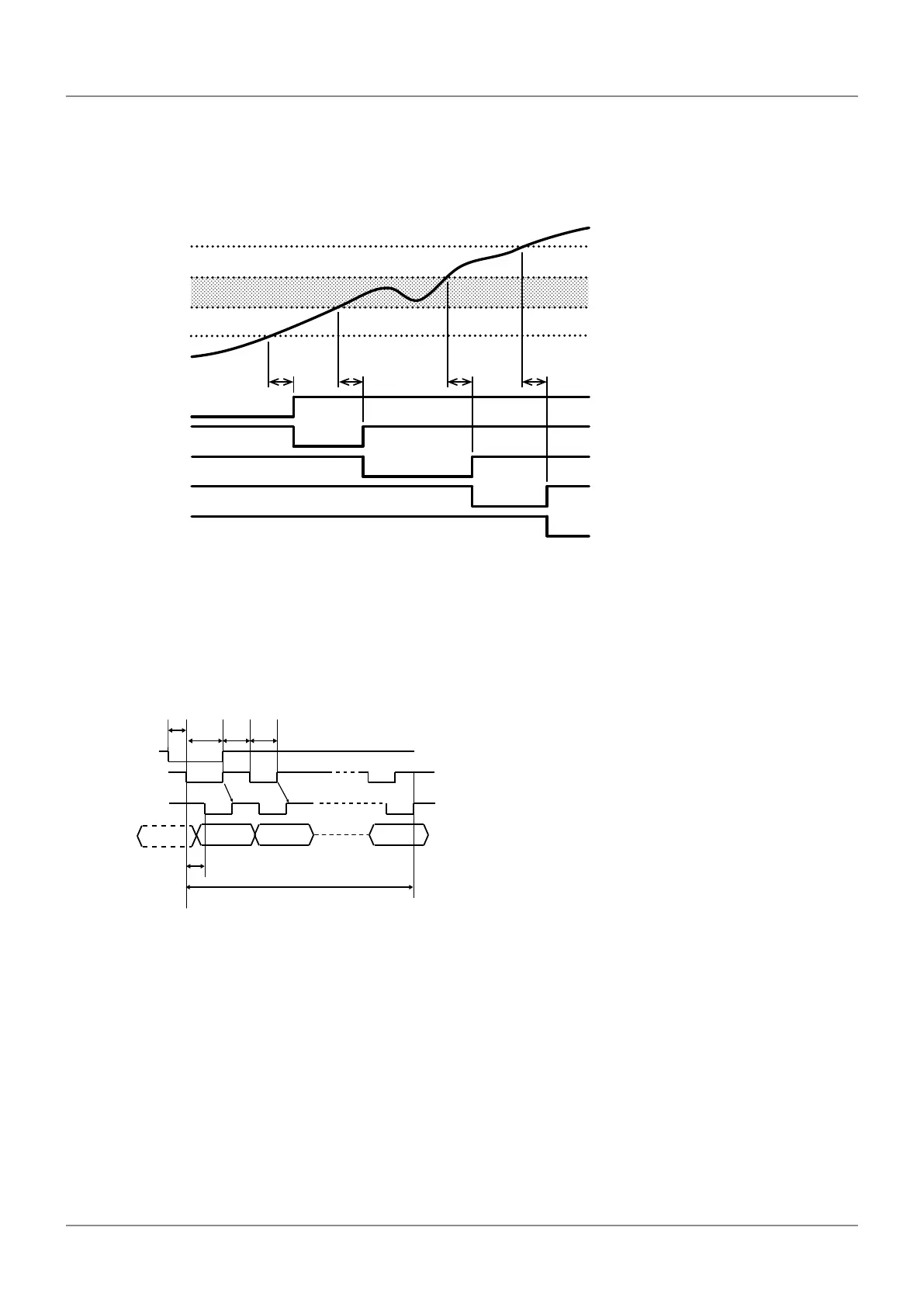
5.5.4 Timing Chart
Tolerance judgment result output
AL1 / BL1
Max. 10 ms
Max. 10 ms
→
AL2 / BL2
AL3 / BL3
AL4 / BL4
AL5 / BL5
S1
S2
S3
S4
Max. 10 ms
Max. 10 ms
Counter data
OK area
Tips
After acquiring the counter data, there is a maximum 10 ms delay before the tolerance judgment result is output.
BCD output
D1 D2 D8
SET1
BCDCK
READY
Max.
5 ms
Min. 10 ms x 8 = 80 ms
Min.
2 ms
Min.
5 ms
Min.
5 ms
Min.
5 ms
Tips
• "SET1" and "BCDCK" (BCD clock) denote input signals, and "READY" denotes the output signal.
• The BCD data (D1, D2 in the gure above) will be modied at the fall of the BCD clock while SET1 is input.
When the BCD data is accepted, the READY signal falls. The time to accept the data after the fall of the
BCD clock is 5 ms maximum. The READY signal rises together with the BCD clock.
• If SET1 is turned to L during data output, the data output is stopped, and then a new data output starts from
D1.
 Loading...