9
2 Setup
No. 99MBC122A
Procedure for mounting to the stand (optional) or xture
1
Loosen the xation screw on the dedicated stand (optional) or other device.
2
Insert the stem into the gage mounting hole.
ø15
+0.034
+0.014
ø15
+0.034
+0.014
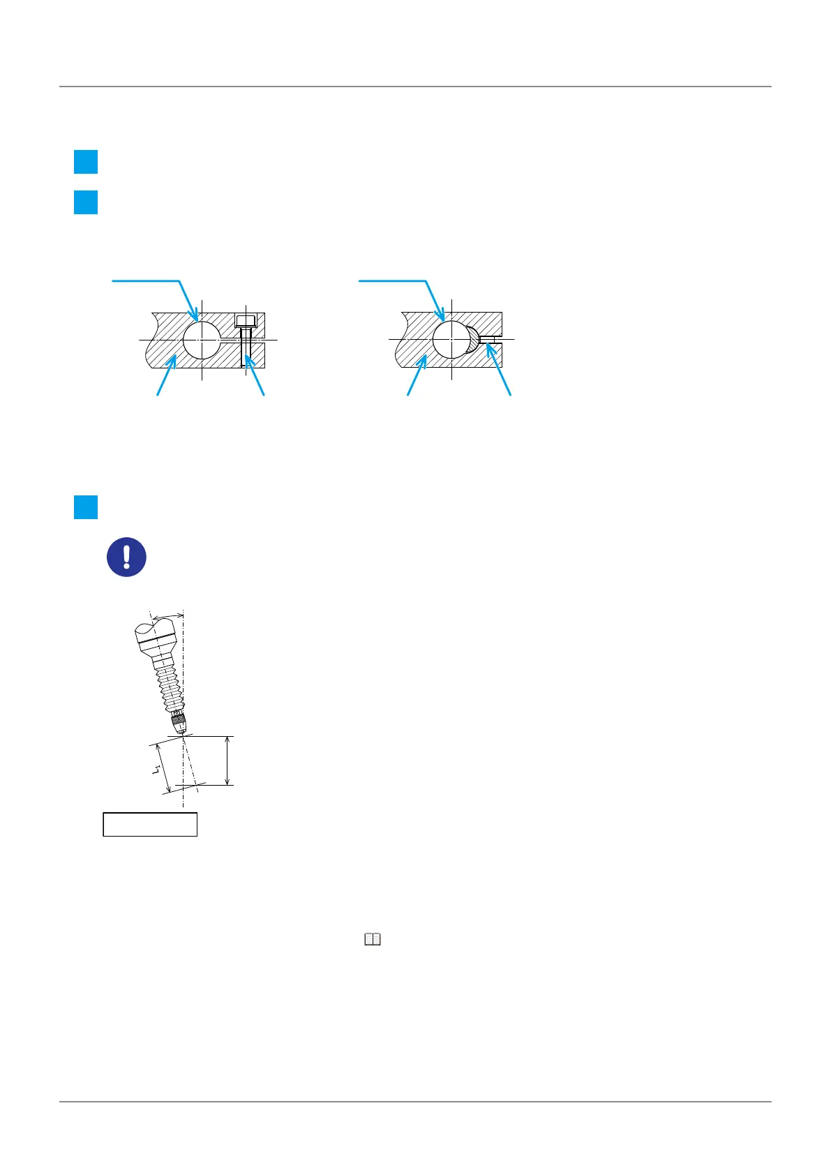
(Gage mounting hole) (Gage mounting hole)
Fixing part Fixing partFixation screw Fixation screw (set screw)
Tips
The above diagrams show examples of how to make a xation part of the gage head.
3
Tighten the xation screw to secure the gage.
Process the gage mounting hole to be parallel to the measurement direction.A tilted gage will result in
a measurement error.
L
0
θ
Error = L
1
-L
0
• To secure the gage, use a tightening torque of approximately 0.5 N・m.Overtightening the stem may cause
malfunction or failure.
• When measuring by moving the gage head, make sure that the cable will not be strained and no excessive
force will be applied to the gage main body. It may cause damage.
For the dedicated stand and other options, see "7.3 Option" (page 62).
 Loading...