49
5 External Input/Output Function
No. 99MBC122A
Pin num-
ber
I/O
Tolerance judgment output mode BCD output mode
Name Functions Name Functions
28 I DISP Displayed BANK specication: In combination with SET. During input, the
decimal point will blink.
29 I MODE Peak switchover: In combination with SET. During input, the decimal point will
blink.
30 I BCDCK BCD output specication: In combination with SET. During input, the decimal
point will blink.
31 I EXTTRG USB trigger
32 I A_HOLD Ach (upper display) display: HOLD
During input, the decimal point will blink.
33 I B_HOLD Bch (lower display) display: HOLD
During input, the decimal point will blink.
34 I HOLD HOLD/Error cancel input
During input, the UNIT indicator will blink.
35 I PA Ach (upper display) Preset/Peak clear (in Peak, HOLD mode)
During input, the decimal point will blink.
36 I PB Bch (lower display) Preset/Peak clear (in Peak, HOLD mode)
During input, the decimal point will blink.
Tips
• For external input, negative logic (L = enabled) is used.
• "I/O" refers to the rst letters of "Input/Output" respectively. Refer to the input circuit for "I", and the output
circuit for "O".
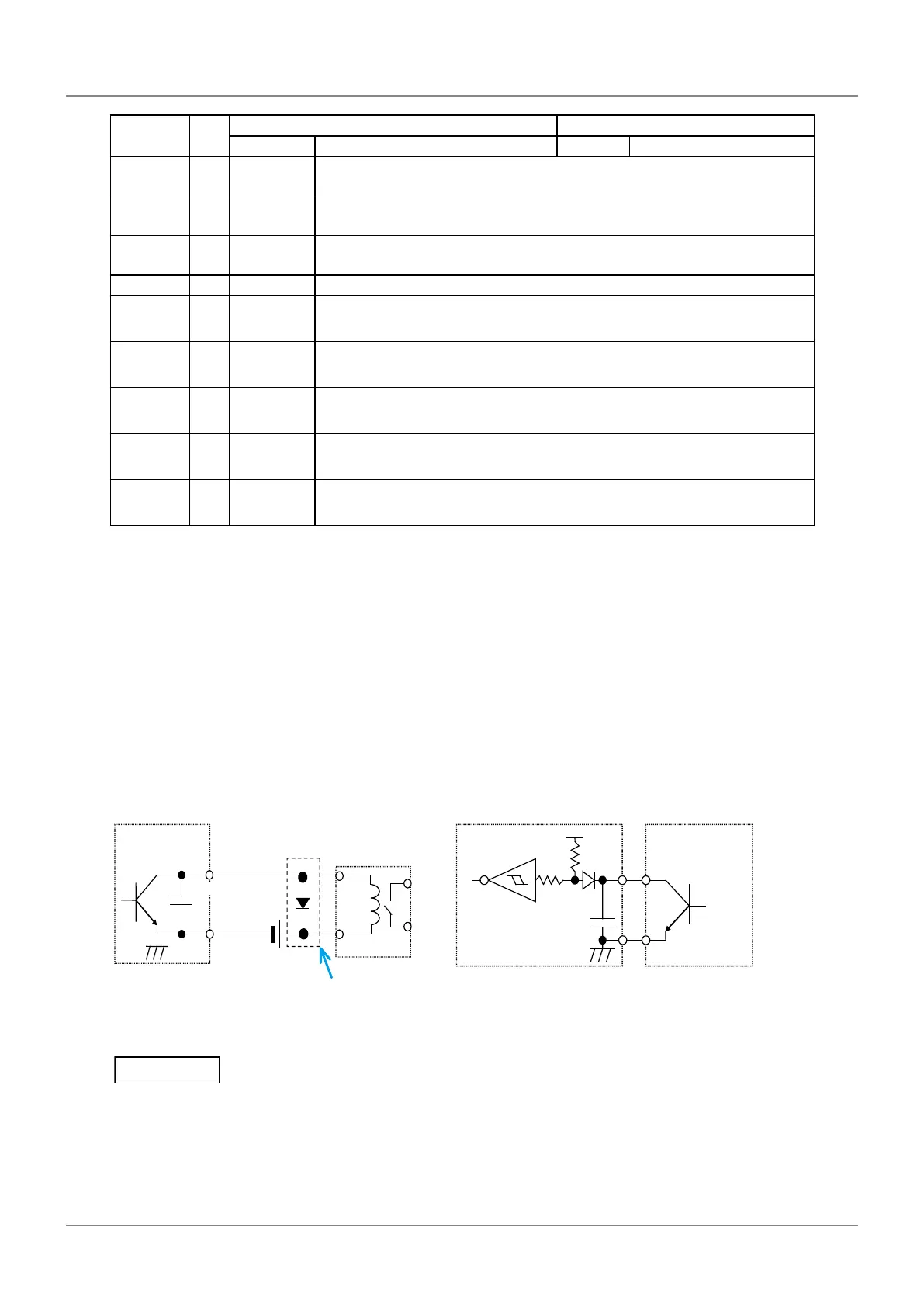
Input/Output circuit
Output circuit Input circuit
Transistor is on when the output is "L" (open
collector).
Input is valid when the input voltage is "L".
COM
0.01 µF
Counter
Output withstand voltage: Max. 24 V
Output current: Max. 10 mA
Output saturation voltage: Max. 0.7 V
Surge current absorbing
diode
60 V, 100 mA or more
TD62583
equivalent
External equipment
Reference circuit
Output
+5 V
5 kΩ
5 kΩ
0.01 µF
External equipment
Reference circuit
Counter
Input current: Max. 2 mA
Input voltage: H = 4 V–24 V
L = Max. 1 V
Use open-collector
output or relay output.
When using relays, incorporate a surge-current-absorbing diode or a protective circuit. If no protection is
incorporated, the IC in the counter may be damaged.
 Loading...