108
T26 System Manual Part 1: Installation
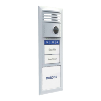
6. Screw on the ‘door lock unlocked/locked’ door lock sensor (coming from the door):
– First wire to IN2 + terminal
– Second wire to IN – terminal
The device still functions properly if the two wires used
here (operating contact and changeover contact) are
swapped.
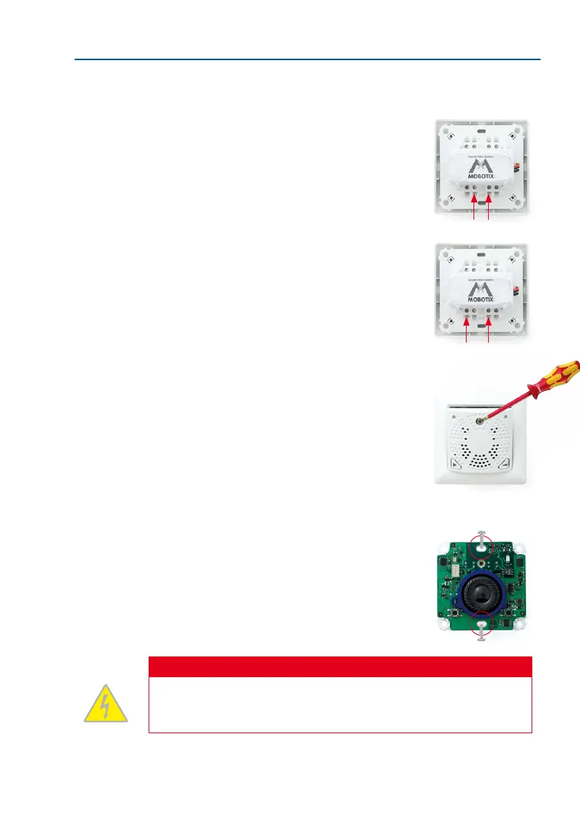
7. Screw on the ‘door opened/closed’ door sensor (reed
switch) coming from the door:
– First wire to IN1 + terminal
– Second wire also to IN – terminal
The device still functions properly if the two wires used
here (operating contact and changeover contact) are
swapped.
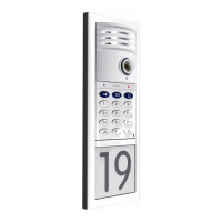
8. Remove the front panel and frame: In order to pro
-
tect the board, the board is attached to the front panel
and frame in the original packaging. To continue with
the installation, however, you must rst separate the
housing and board from the panel and frame. Loosen
the screw in the front panel and li the panel forwards.
Now remove the attached frame from the board. Please
note that you will need the stainless steel screw in the front
panel again later.
9. Insert the housing and circuit board into the socket:
The two cable clamps on the rear of the housing are
located at the top. When using a cavity socket, make
sure you only use the stainless steel screws provided.
Using dierent (larger) screws could damage the board.
Caution
Electrical systems and equipment may only be installed, modied and maintained by
a qualied electrician or under the direction and supervision of a qualied electrician
in accordance with the applicable electrical guidelines.