40
T26 System Manual Part 1: System Overview
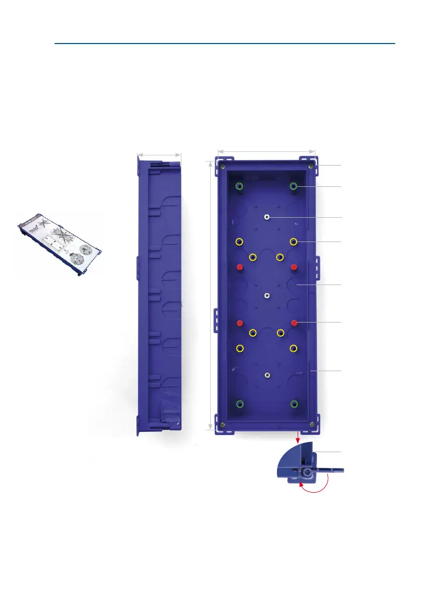
In-Wall and Cavity Housing (Fig. Triple Housing)
The blue housing is rmly connected to the subsurface or brick work. It can also be used to
ensure easy installation in cavities: Drill opening, position housing and screw tightly in
place; the retaining wings, which automatically swing out, secure the housing, while the
plastic bars at the edge of the housing prevent it from sliding into the cavity.
52 mm/2.05 in
Mounting points for termi-
nal board or IO Module (3x)
Plastic bars (6x)
Cable guide (14x)
Mounting points for
cable binders
(8x, marked yellow)
Mounting points for module
frames (4x, marked green)
Do not use the four red
holding xtures for module
frames
Mounting points for gasket
318 mm/12.52 in (double housing: 218 mm/8.58 in, single housing: 129 mm/5.08 in)
117 mm/4.61 in
Retaining wings for cavity
installation (4x)
The insert prevents the
in-wall housing from getting
dirty or being deformed
during installation
The required integration
opening has the following
dimensions (width x height):
Single housing:
117 x 129 mm/4.61 x 5.08 in
Double housing:
117 x 218 mm/4.61 x 8.58 in
Triple housing:
117 x 318 mm/4.61 x 12.52 in