Troubleshooting Reference
2-39
element
TM
Series
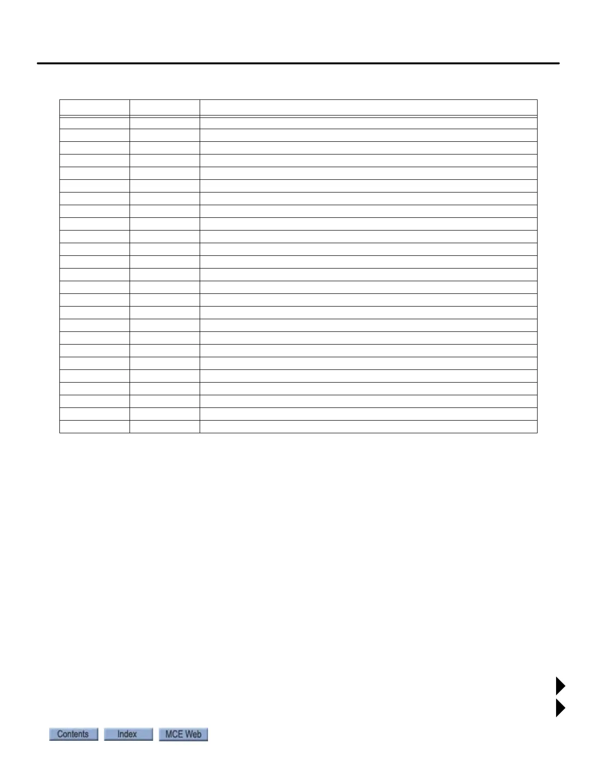
J5 SP3A Position bit
J5 DZR M Door Zone Rear
J5 SP4A Position bit
J5 CGND Pins 9 and 10. Chassis ground.
J6 CANH2 CAN port 2, H
J6 CANL2 CAN port 2, L
J6 DZF M Door Zone Front
J6 CANH1 CAN port 1, H
J6 12V BAT 12V, Battery output
J6 CANL1 CAN port 1, L
J6 DGND Ground
J6 V UNREG Unregulated ~24V
J6 CGND Pins 9 and 10. Chassis ground.
J7 SNN1 Unused
J7 V UNREG Unregulated ~24V from machine room
J7 CANH2 CAN port 2, H
J7 CANL2 CAN port 2, L
J7 Pins 4, 6 Ground
J7 M1, M2 Chassis ground
J8 SNN 2 Unused
J8 V UNREG Unregulated ~24V from machine room
J8 CANH2 CAN port 2, H
J8 CANL2 CAN port 2, L
J8 Pins 4, 6 Ground
J8 M1, M2 Chassis ground
Table 2.8 SCE-CON Connector Assignments
Connector Assignment Description