Installation
1-34 Manual # 42-02-2P26
Install the Bottom Terminal Magnets Refer to Figure 1.11.
1. Place a 30-inch, striped magnet to the left of the tape perforations, just above the bot-
tom door zone magnet as shown above. The bottom of the 30-inch magnet must be even
with the top of the door zone magnet.
2. Stack one 5-inch striped magnet directly below the Front Door Zone magnet. Leave no
gaps between the ends of the magnets.
3. Once the hoistway has been successfully learned and door zone magnet placement is
satisfactory, you may “lock” the magnets in place by placing a drop of silicone adhesive
immediately above the top end and immediately below the bottom end of each magnet.
ETS/ETSL magnets and/or switches Refer to Figure 1.11.
ETS/ETSL switches may be required where reduced-stroke buffers are used or where full-
stroke buffers are used and the rated speed is greater than 200 fpm/1.0m/s. These options are
described in Terminal Switch Configuration on page 1-56 and the procedure used to determine
the location of the switches is described in Terminal Switch Learn on page 1-57.
The floors must be learned, see “Hoistway Learn (Landing System Learn)” on page 1-52 and it is
recommended to adjust the drive, see “Drive Response” on page 1-53 before performing the
Terminal Switch Learn procedure and installing the ETS/ETSL magnets/switches.
Electrical Connection
Make electrical connections as shown in the job prints. Element installations use the DISC (dis-
crete) and M-CAN connections.
Secure cables with a nylon tie wrap through the holes provided. VERY IMPORTANT as this
provides strain relief and prevents connector fatigue over time.
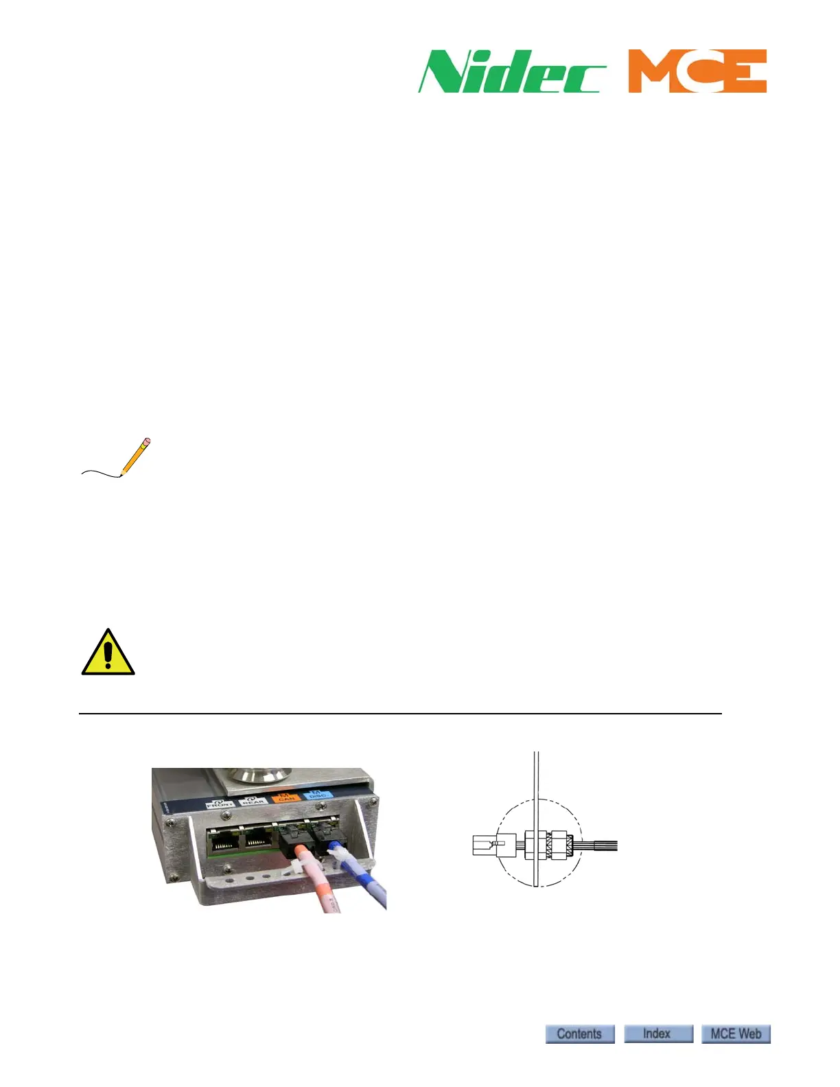
Figure 1.12 Sensor Connections
Element CAN & Discrete, 1 orange and 1 blue
cable
The NEMA 4X / 12
version provides
strain relief and
sealed entry using a
gasketed cover and
special hardware as
shown.