Installation
1-42 Manual # 42-02-2P26
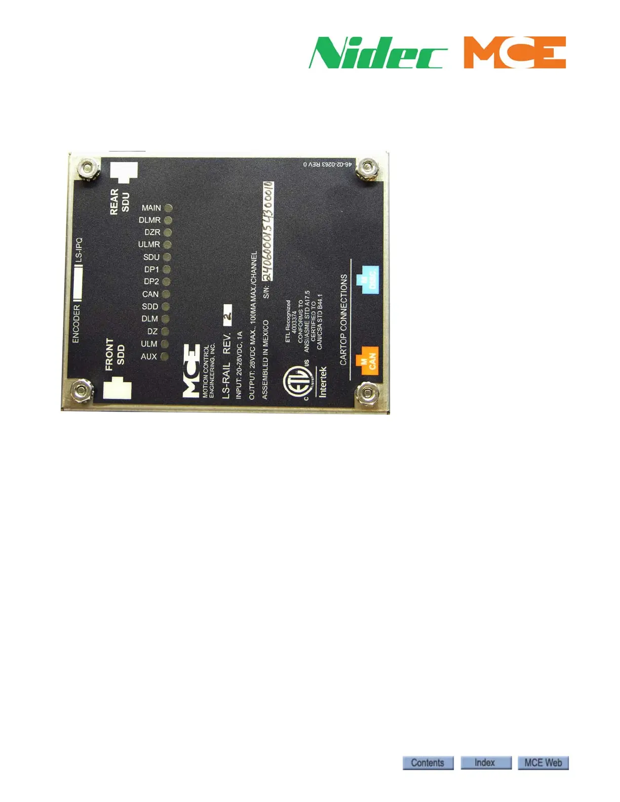
Indicators
Lighted indicator LEDs on top of the sensor unit provide information about active signals.
Figure 2. Indicator LEDs
• DP1, DP2: Quadrature pulses (iControl). DP1 leads when the car is traveling up. DP2 leads
when the car is traveling down. Alternately active whenever the car is in motion.
• CAN: Motion 2000/4000 or Element CAN communication with landing system is active.
Permanently Attach Magnets
Once the hoistway has been successfully learned and door zone magnet placement is satisfac-
tory, you may “lock” the magnets in place by placing a drop of silicone adhesive immediately
above the top end and immediately below the bottom end of each magnet.
MAIN: Sensor processor A active.
DLMR: Down Level Marker Rear.
DZR: Door Zone Rear.
ULMR: Up Level Marker Rear.
SDU: Slow Down Up.
DP1:Quadrature pulse.
DP2: Quadrature pulse.
CAN: CAN communication activity.
SDD: Slow Down Down.
DLM: Down Level Marker (Front).
DZ: Door Zone (Front).
ULM: Up Level Marker (Front).
AUX: Sensor processor B active.