Installation
1-46 Manual # 42-02-2P26
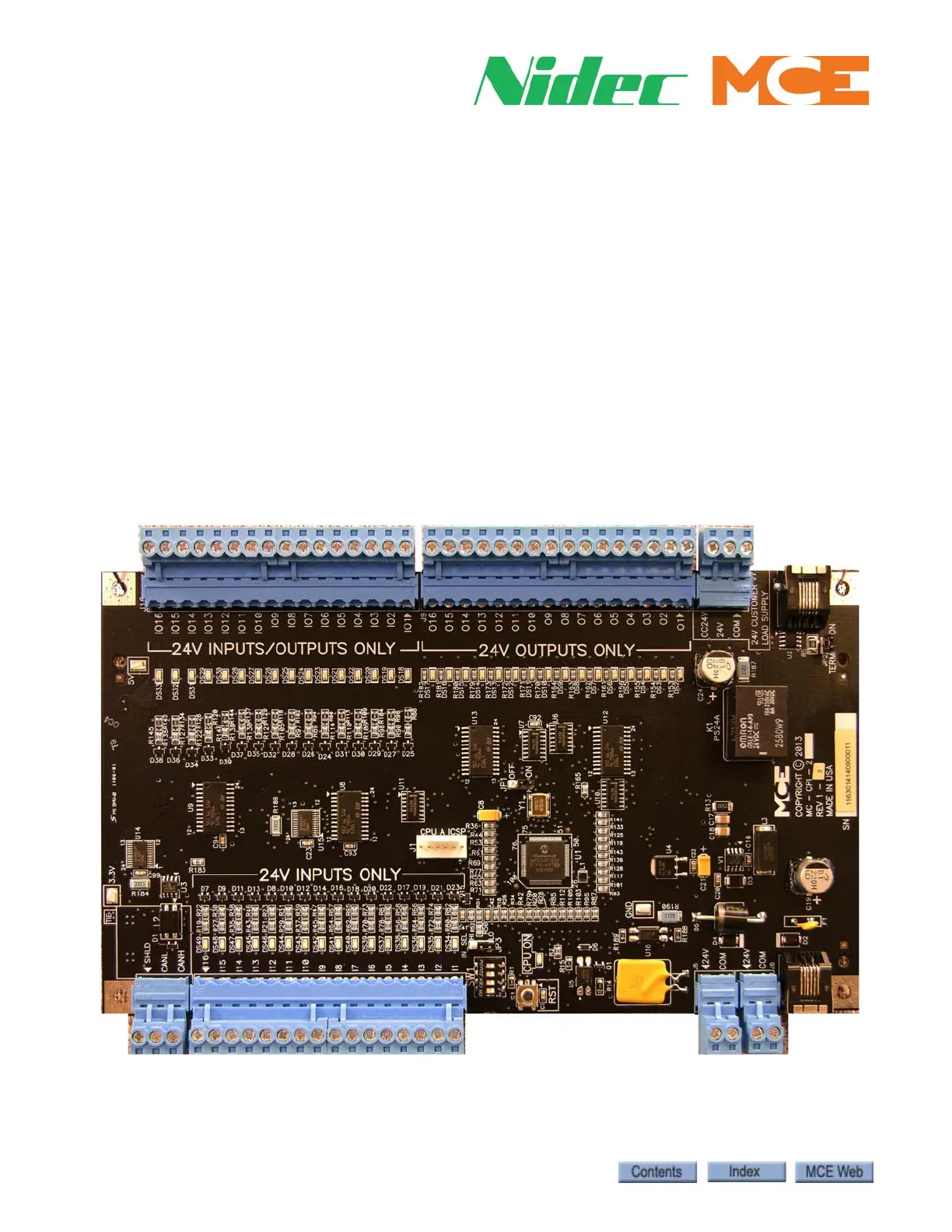
Serial Car Call Board
The MC-CPI-2 board, mounted in the car operating panel, converts the discrete closures from
the panel buttons and switches to serial data for the CAN bus. Unused spare inputs to and out-
puts from these boards are set to NOT USED at the factory. If a CPI-2 board is replaced in the
field or if controller software is upgraded, it is very important to check programmable CPI-2
board inputs and outputs and verify unused connections are set to NOTUSED. The CPI-2 board
is also responsible for landing system control. For additional information, please refer to
page 2-35.
Installation Instructions
1. Turn the power off at the main disconnect.
2. Mount the MC-CPI-2 board(s) inside the COP using the supplied hardware and provid-
ing sufficient clearance for the components. Verify board address, page 1-49.
3. CAR CALL indicator LEDs or lamps must be powered from the CC24V supply. Other
lamps, PIs, and buzzers must be powered from the 24V supply. Button contacts are gen-
erally connected to Common and to their specific I/O terminal.
4. Refer to the job prints to wire the MC-CPI-2 board.
Figure 1.2 MC-CPI-2 Serial Car Operating Panel Board