Tape Installation
1-35
element
TM
Series
Parameter Settings
Verify touch screen Config 01, Building Setup information is correct.
Hoistway Learn
Please refer to “Hoistway Learn (Landing System Learn)” on page 1-52.
Offset
All compatible controllers allow the door zone heights to be individually adjusted in 0.10 inch
increments to compensate for magnet placement irregularity. Please refer to CONFIG02, Hoist-
way Setup.
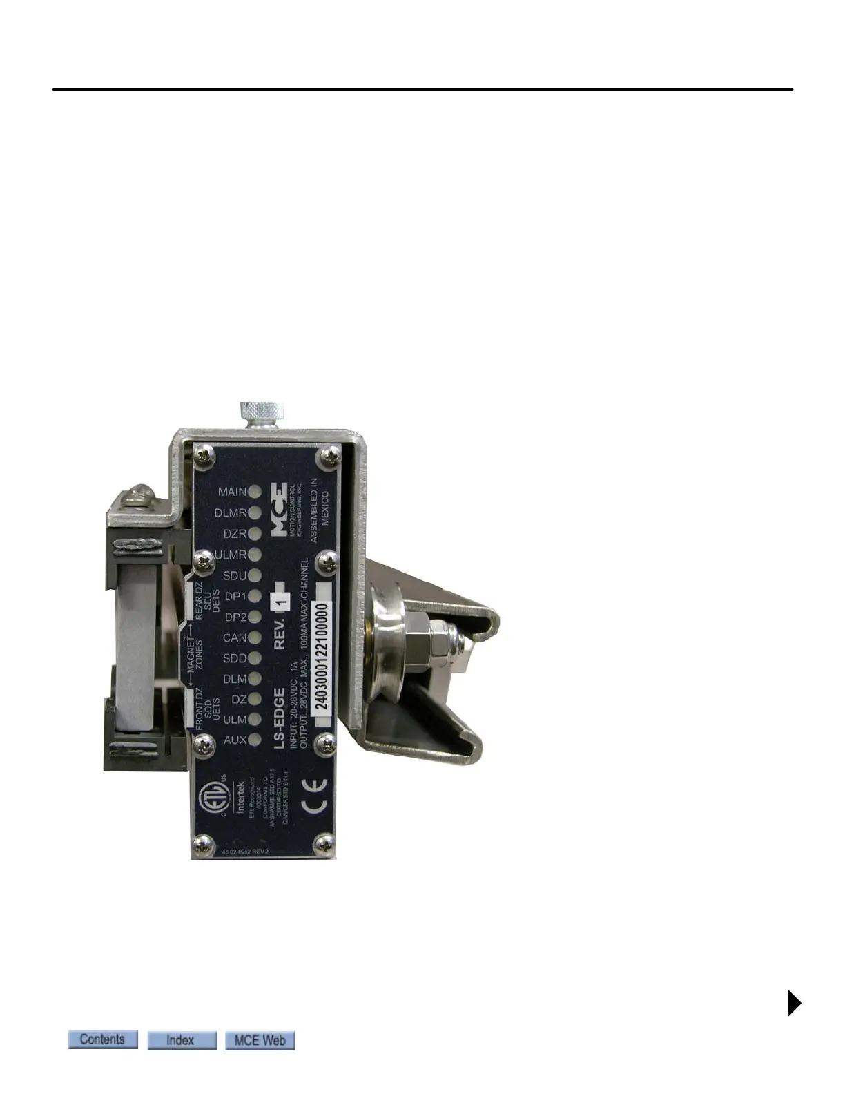
LS-EDGE Indicators
Lighted indicator LEDs on top of the sensor unit provide information about active signals.
Figure 1.13 Indicator LEDs
• DP1, DP2: Quadrature pulses. DP1 leads when the car is traveling up. DP2 leads when the
car is traveling down. Alternately active whenever the car is in motion.
• CAN: CAN communication with landing system is active.
MAIN: LED blinks- processor A active.
DLMR: Down Level Marker Rear.
DZR: Door Zone Rear.
ULMR: Up Level Marker Rear.
SDU: Slow Down Up.
DP1:Quadrature pulse.
DP2: Quadrature pulse.
CAN: CAN communication activity.
SDD: Slow Down Down.
DLM: Down Level Marker (Front).
DZ: Door Zone (Front).
ULM: Up Level Marker (Front).
AUX: Sensor processor B active.