Configuration and Troubleshooting
2-38 Manual # 42-02-2P26
SCE-CON Board
The SCE-CON board is an interface between car-mounted equipment and the elevator control-
ler. The SCE-CON board is connected to the elevator controller using a CAN serial connection
and additional conductors as required through the traveller and connects to the landing system
and car call serializing boards through local CAN and discrete connections.
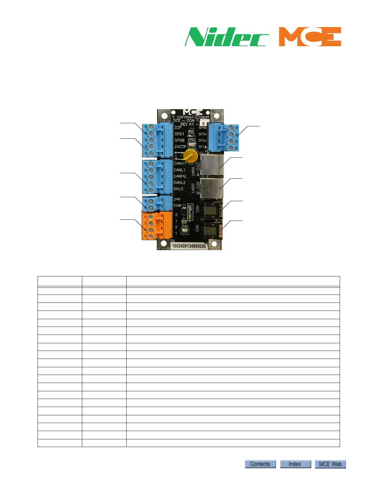
Figure 3. SCE-CON Connector Board
Table 2.8 SCE-CON Connector Assignments
Connector Assignment Description
J1 SPD0 Speed bit 0 from the LS-EDGE landing system
J1 SPD1 Speed bit 1 from the LS-EDGE landing system
J1 DZF Front Door Zone signal from the LS-EDGE landing system
J1 24CTP 24VDC fused power out (F1 is 72V, 1100mA)
J2 CANH1 CAN port 1, H
J2 CANL1 CAN port 1, L
J2 CANH2 CAN port 2, H
J2 CANL2 CAN port 2, L
J2 SHLD CAN shield
J3, Pin 1 2 120VRMS from machine room
J3, Pin 2 1 Ground
J3, Pin 3 2 120VRMS to load weigher
J3, Pin 4 1 Ground
J4 24V 24V to first MC-CPI-2 board
J4 COM Common for 24V
J5 SPD0 Speed bit 0 from LS-EDGE sensor
J5 SPD1 Speed bit 1 from LS-EDGE sensor
J5 SPD2 Speed bit 2 from LS-EDGE sensor
J5 SP1A Position bit
J5 SP2A Position bit
See job prints
Landing System IO
Landing System IO
Local CAN
Local CAN
Landing System IO
External CAN
24V Output to COP Board
1 (ground) and 2 (110VAC)
24VDC Supply from controller