Installation
1-44 Manual # 42-02-2P26
Addressing and CAN Bus Termination Set SC-3HN addresses as shown in the job
prints for the installation. Generic examples are provided below.
Riser Assignment Element supports only one hall riser.
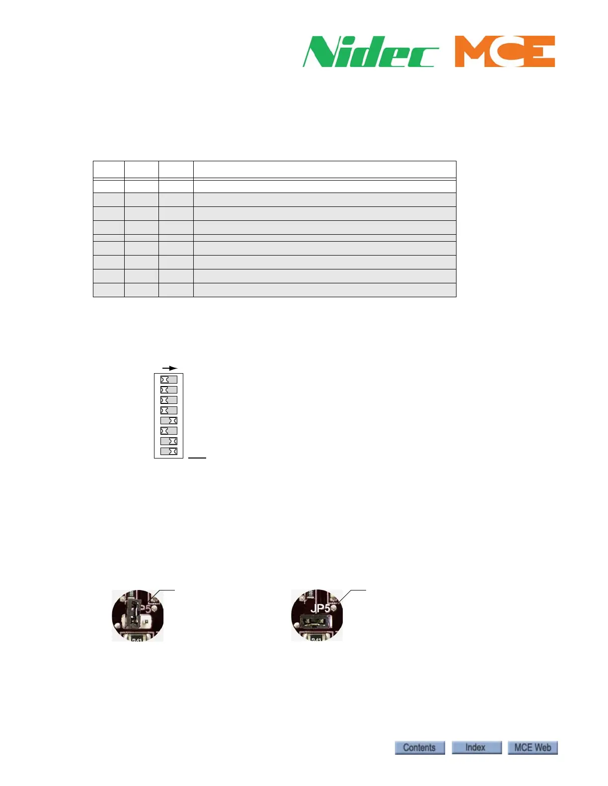
Floor Number and Front or Rear Opening DIP switch SW1, switches 1 through 7
set the floor address for the board, beginning with Floor 1. Switch 8 selects Front or Rear open-
ing (ELEMENT uses FRONT OPENINGS ONLY).
Baud Rate Jumper JP4 is reserved for future use to select a different CAN Bus baud rate
should it become necessary. For now, the only option is to leave the JP4 jumper in place, setting
baud rate to 125 kbps.
CAN Bus Termination The CAN Bus must be terminated ONLY ON THE LAST SC-
3HN connected to the wire drop (farthest board from Dispatcher).
Table 1.1 Riser Assignment by Jumper Binary Representation
JP3 JP2 JP1 Riser
1 1 1 Main A (Binary value 7) USE FOR ELEMENT.
1 1 0 Main B (Binary value 6)
1 0 1 Main C (Binary value 5)
1 0 0 Main D (Binary value 4)
0 1 1 Auxiliary A (Binary value 3)
0 1 0 Auxiliary B (Binary value 2)
0 0 1 Auxiliary C (Binary value 1)
0 0 0 Auxiliary D (Binary value 0)
64
32
16
8
4
2
1
SW
8
7
6
5
4
3
2
1
ON
Floor address example = 11
ON switch adds its value to floor address.
OFF=FRONT, ON=REAR
When setting addresses, use the values silk-
screened on the circuit board, not those shown
on the DIP switch.
JP5 OFF/Unterminated
All but last board
JP5 ON/Terminated
Last board on wire drop ONLY.