Installation
1-56 Manual # 42-02-2P26
Terminal Switch Configuration
The Element controller’s “Terminal Switch Learn” is used to configure virtual NTS/ETS/ETSL
switches and to determine optimal placement of physical switches and magnets. Before posi-
tioning physical ETS/ETSL switches in the hoistway or ETS-LS magnets on the tape or rail, con-
figure the controller with VIRTUAL NTS and ETS switches (CONFIG02 > ETS Switches). Then
using (UTIL > LANDING SYSTEM UTILITIES > TERMINAL SWITCH LEARN), enter the
desired percentage of rated car speed at which the car should be traveling when each switch is
encountered. Follow on-screen instructions for learning terminal switch configuration.
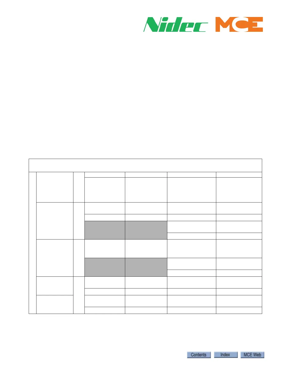
In the following table, enter the values generated for each of the switches and place physical
switches and/or magnets accordingly. Where physical switches and/or landing system magnets
are used for ETS/ETS-LS/ETSL, these will need to be enabled in the CONFIG02 > ETS switch
screen and the Terminal Switch Learn process will need to be repeated before the Safety Tests
are done and the car is turned over.
Note: For reduced stroke buffers, the Terminal Switch Learn process will need to be done twice
to generate recommended distances and speeds for both ETS magnets on the landing system
tape (ETS-LS) and ETSL cam-actuated switches in the hoistway (see Terminal Switch Learn on
page 1-57).
* Where magnets are placed on the tape as an ETS backup, manually enter the UETS/DETS speed in the
CONFIG 02 > ETS Switches > U/DETS-LS OVERSPEED box.
** For reduced stroke buffers only. ETSL % = ETS % x Rated Buffer Speed/Rated Car Speed
Table 1.2 Recommended Emergency Terminal Switch Configuration Calculation
Caution: When performing the ETSLD test, be sure that the speed entered for the test [UTILS > SAFETY TESTS >
COMLIANCE TESTING > SPEED] does not exceed the rated buffer speed.
UTIL > LANDING SYSTEM UTILITIES > TERMINAL SWITCH LEARN
“SWITCH”
and desired
percentage of car
speed when
switch is
actuated
Screen
DISTANCE (in.) LEARNED SPEED DELTA SPEED (fpm) TEST SPEED (fpm)
Choose the lesser
distance (top or
bottom) from the
terminal landing for
“switch” placement
Choose the greater
learned speed (up or
down)
These are typically the
same, but choose the
lesser where there is a
difference.
Add the learned speed
+ delta speed
+ 5 fpm
NTS1
____%
(78% typical)
(Closest switch
to terminal
landing)
CONFIG 02
NTS1 Switches
USL1 Distance/
DSL1 Distance
USL1 Speed/
DSL1 Speed
USL1 Delta-L Speed/
DSL1 Delta-L Speed
USL1-L Test Speed/
DSL1-L Test Speed
USL1 Delta-H Speed/
DSL1 Delta-H Speed
USL1-H Test Speed/
DSL1-H Test Speed
NTS2
____%
(74% typical)
CONFIG 02
NTS2 Switches
USL2 Distance/
DSL2 Distance
USL2 Speed/
DSL2 Speed
USL2 Delta-L Speed/
DSL2 Delta-L Speed
USL2-L Test Speed/
DSL2-L Test Speed
USL2 Delta-H Speed/
DSL2 Delta-H Speed
USL2-H Test Speed/
DSL2-H Test Speed
ETS
____%
(90-95%)
CONFIG 02
ETS Switches
UETS Distance/
DETS Distance
UETS Speed/
DETS Speed*
UETS Delta Speed/
DETS Delta Speed
UETS Test Speed/
DETS Test Speed
ETSL**
____%
UETS Distance/
DETS Distance
UETS Speed/
DETS Speed
UETS Delta Speed/
DETS Delta Speed
UETS Test Speed/
DETS Test Speed