User Interface
1-11
element
TM
Series
User Interface
System status display, configuration, and diagnostics are through the on-board, color, touch-
screen (OBD - On Board Display).
1
No external programming tools are required. You must be
on Inspection mode to change and save parameters. The interface provides:
•Home, page 1-11
• Config 01, 02, and 03, page 1-13
•Utils, page 1-14
• System IO, page 1-14
• System Diag, page 1-14
•SPA Diag, page 1-15
•SPB Diag, page 1-15
•SPC Diag, page 1-15
•PLD Diag, page 1-15
•Action Info, page 1-15
• Status Info, page 1-16
• Stats, page 1-16
•Scope, page 1-16
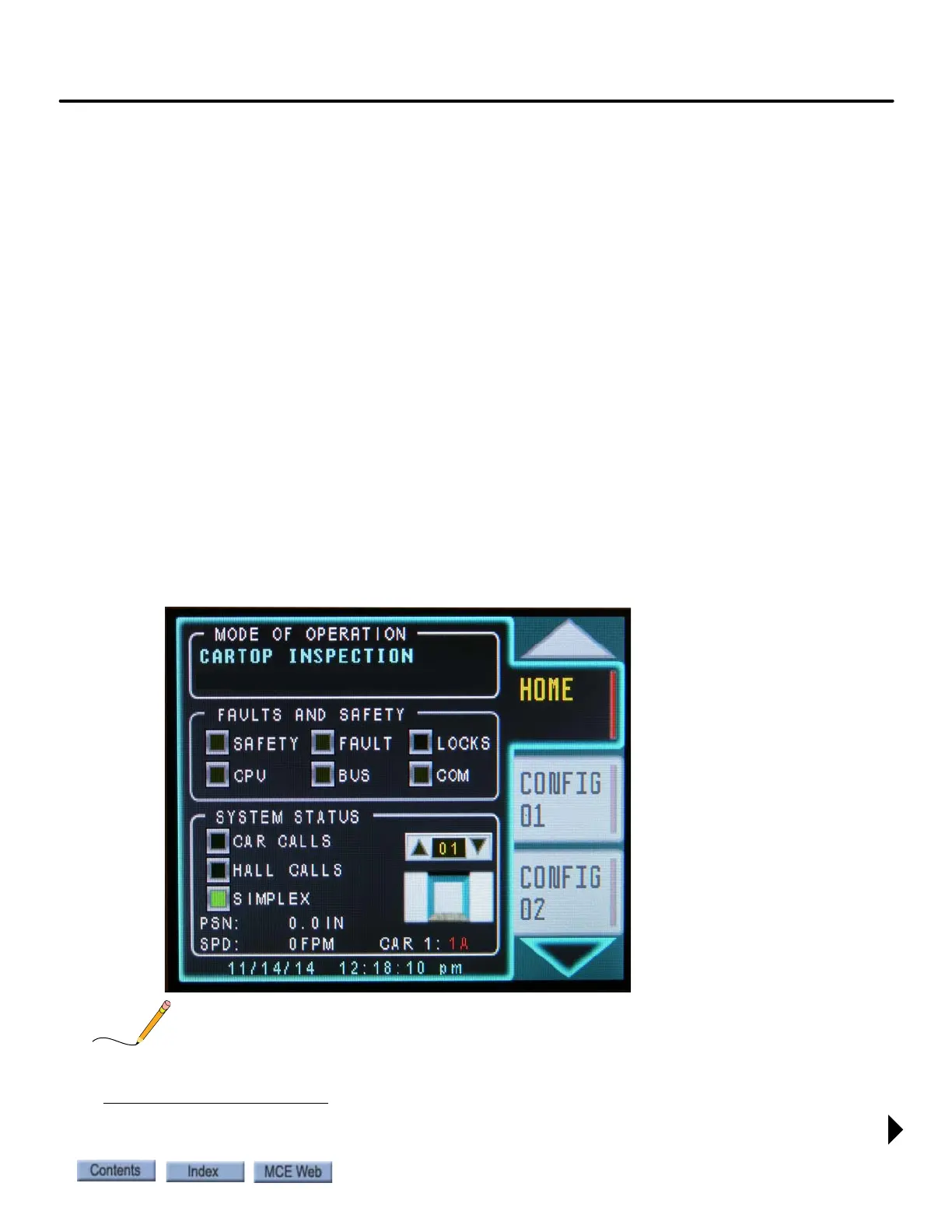
Home Screen
Figure 1.2 Home Screen
For detailed parameter descriptions, see Screen Descriptions on page 2-5.
1. Web browser access is supported. Parameters may be transferred from controller to controller using a USB drive.