LS-EDGE Landing System
1-27
element
TM
Series
LS-EDGE Landing System
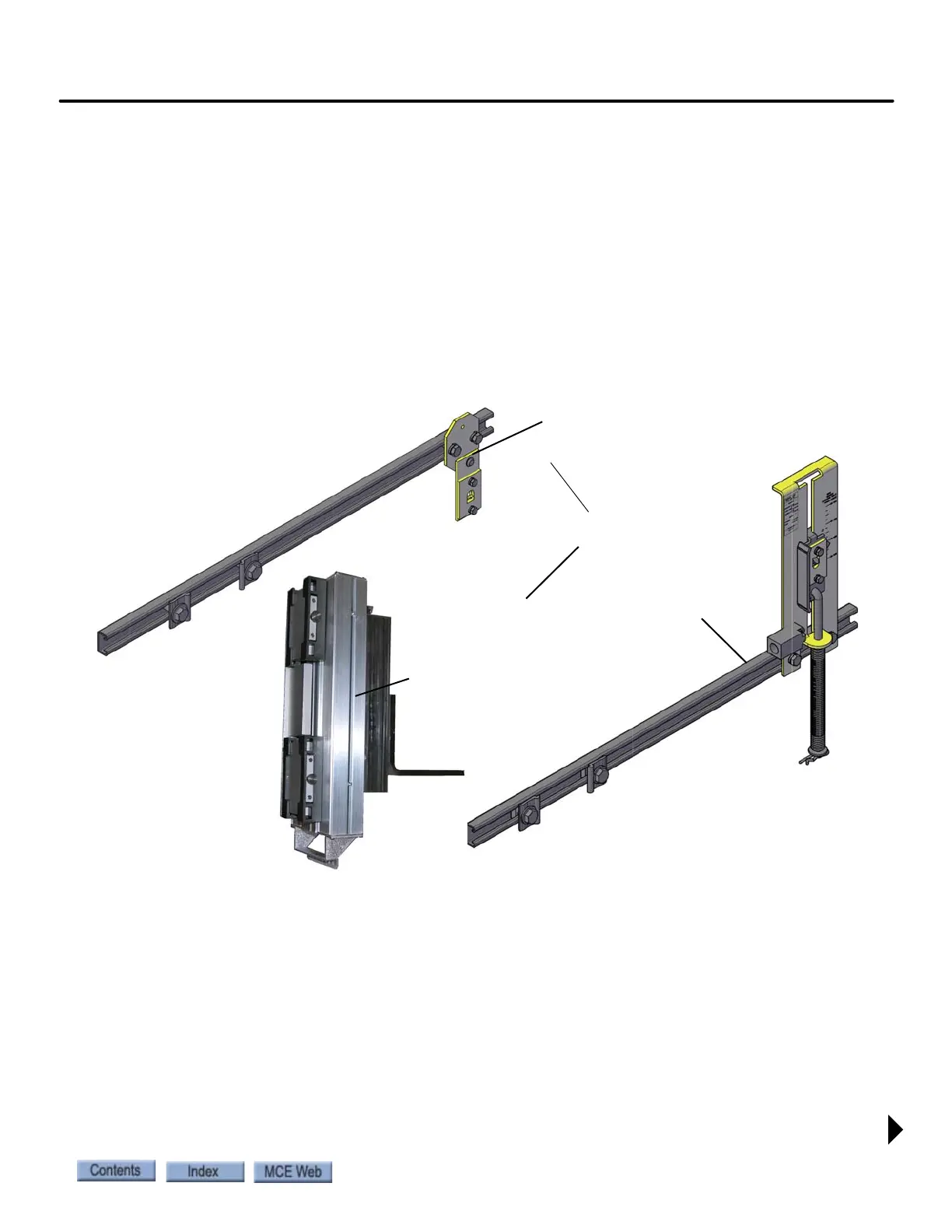
The LS-EDGE kit contains the sensor head assembly, an “L” bracket to mount the sensor
assembly to a uni-strut that is in turn attached to the elevator cab (uni-strut to elevator cab not
provided), steel tape, top and bottom steel tape hanger assemblies, the required number of door
zone magnets, and the CAT-5 electrical cables required to connect the sensor to the interface
board.
Depending on applicable code, you may have to route electrical connections through conduit. If
so, we recommend minimum 3/4-inch flex so that the modular connectors can slide through
without binding. Perforations for cable tie wrap connection are provided on the RJ-45 plug-end
of the sensor head.
Figure 1.6 LS-EDGE Component
Together, these are assembly
LS-TAPEMNT-EDGE
Steel tape, magnets & connecting cables not shown
Top hanger assembly
(diagonal brace not shown)
LS-TAPEMNTOP-EDGE
Sensor assembly
LS-EDGE
Bottom hanger assembly
LS-TAPE MNTBOT-EDGE