Installation
1-40 Manual # 42-02-2P26
Terminal Magnets
Element controllers use terminal magnets. Follow the instructions below.
Top and Bottom Terminal
Magnets marked with a stripe to differentiate them from the door zone magnets are used at the
top and bottom terminals. 5-inch striped magnets are also used for physical ETS when required
(if reduced stroke buffers are used, cam operated ETSL switches may also be required).
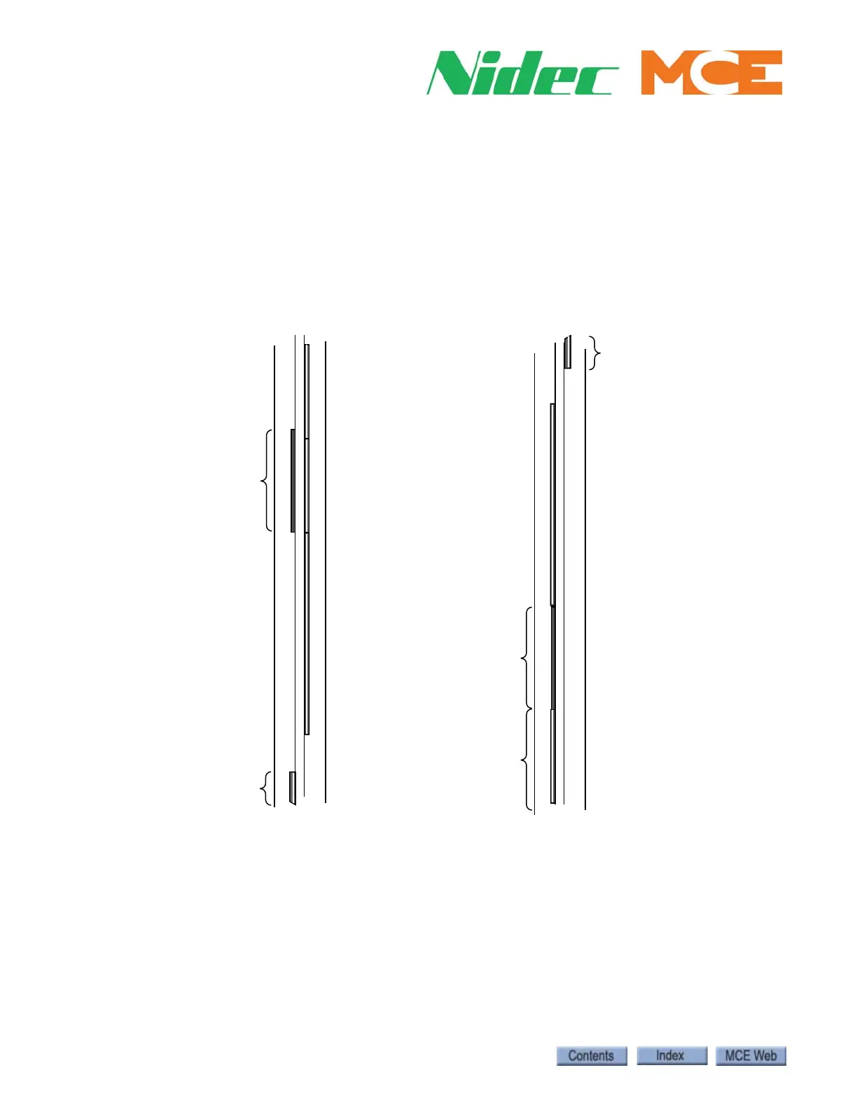
Figure 1.16 Top Terminal and Bottom Terminal Magnets
Install the Top Terminal Magnets Refer to Figure 1.16
1. Place a 30-inch, striped magnet in the right rail angle, just below the top door zone mag-
net as shown above. The top of the 30-inch magnet must be even with the bottom of the
door zone magnet.
2. For jobs with front doors only stack two 5-inch striped magnets above the 30-inch mag-
net. Leave NO GAPS between the striped magnets.
FRONT
ONLY
5” STRIPED
MAGNET
5” STRIPED
MAGNET
Bottom aligned
with bottom of DZ
magnet
5” STRIPED
ETS MAGNET
IF ETS
MAGNETS
USED
30” STRIPED
MAGNET
5 1/2” F DZ
MAGNET
FRONT
ONLY
5” STRIPED
MAGNET
Top aligned
with bottom
of DZ
magnet
5” STRIPED
ETS MAGNET
IF ETS
MAGNETS
USED
30” STRIPED
MAGNET
5 1/2” F DZ
MAGNET
BOTTOM TERMINAL
TOP TERMINAL