Tape Installation
1-31
element
TM
Series
Sensor Installation
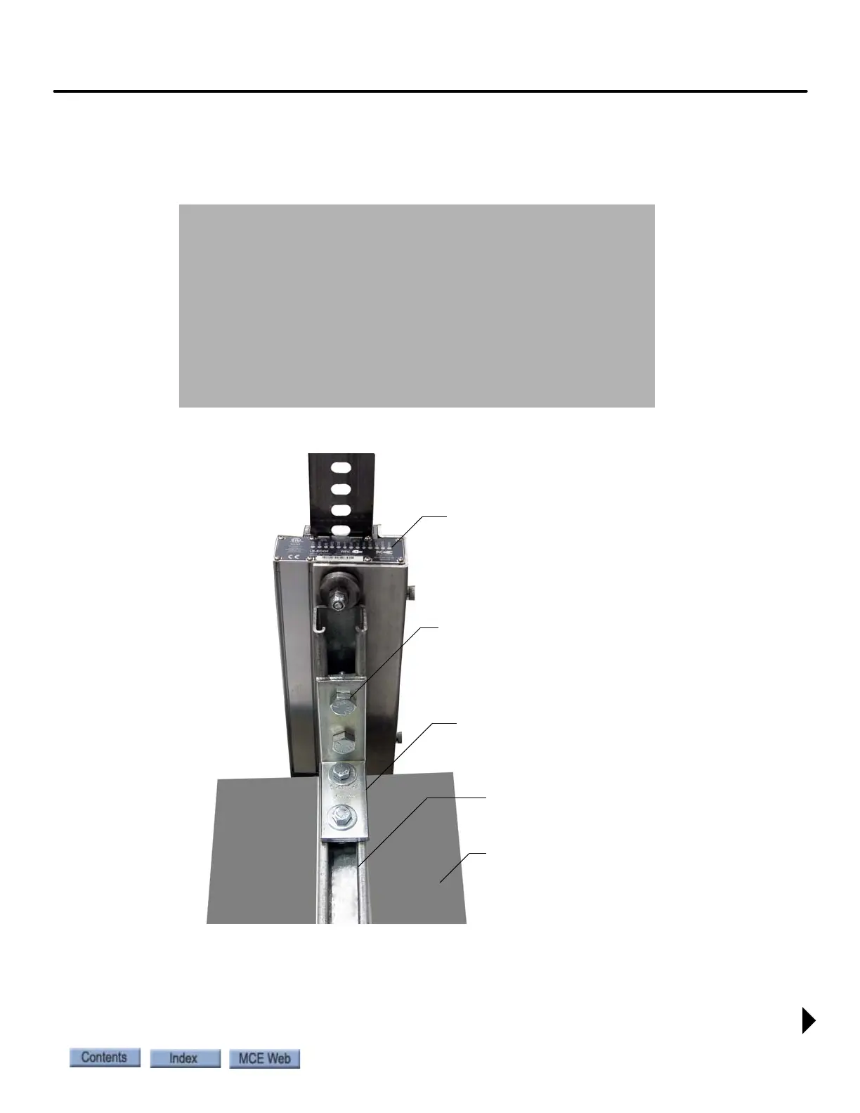
Tape guide side pieces easily detach so the sensor can be slipped onto the steel tape.
Figure 1.8 Sensor with Guide Sides Removed
Figure 1.9 Sensor Mounting
Sensor Alignment
After the tape has been installed, check the sensor alignment. The sensor should not ride hard
on either side of the uni-strut bracket during any part of travel through the hoistway. In high-
rise buildings, if rail alignment varies substantially, it may cause the encoder guides to wear
prematurely. If such misalignment is noted, the installation should be inspected more regularly.
Customer provided uni-strut
CAR TOP
“L” bracket (provided)
LED Indicators UP
40 - 50 ft lbs