Installation
1-38 Manual # 42-02-2P26
Electrical Connections
Make electrical connections as shown in the job prints. Element installations use the DISC (dis-
crete) and M-CAN connections.
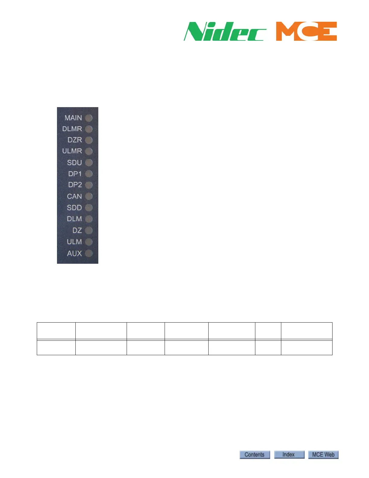
Diagnostic LEDs
Hoistway Limits and Slowdowns
The following table lists the required equipment for the LS-RAIL. “Count” indicates informa-
tion derived from the LS-RAIL.
Virtual Switches
Generally, when the LS-RAIL landing system is chosen, it is so that many switches may be posi-
tioned in software and not physically mounted in the hoistway. The same is true when the LS-
EDGE steel tape landing system is chosen.
Table 2. Hoistway Equipment Per Controller
Controller
Terminal
Slowdowns
Directional
Limits
Finals
Intermediate
Stepping
Access
Limits
ETS (<200FPM)
Element
Traction
Count Count Physical Not Supported Count Count & Magnet
(SPD 0/1)
MAIN: Sensor processor active
DLMR: Down Level Marker Rear
DZR: Door Zone Rear
ULMR: Up Level Marker Rear
SDU: Slow Down Up
DP1: Quadrature pulse
DP2: Quadrature pulse
CAN: CAN communication active
SDD: Slow Down Down
DLM: Down Level Marker (Front)
DZ: Door Zone (Front)
ULM: Up Level Marker (Front)
AUX: Sensor processor active