ioThinx 4510 Series Hardware Installation
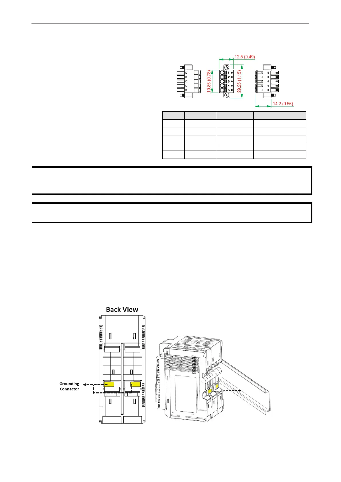
Wiring Serial Port(s)
Wire range: 16 to 28 AWG (Ferrule diameter:
1.2 to 0.3 mm)
Wire strip length: 9.0 mm
Pin RS-232 RS-422 RS-485 (P1/P2)
1 TXD TXD+ DATA1+
2 RXD TXD- DATA1-
3 RTS RXD+ DATA2+
4 CTS RXD- DATA2-
5 GND GND GND
Connect the signal common
pin (e.g. GND pin on the serial port pin assignment) between each of the serial
device units. For insulated wire (shielding cable)
that is used to reduce electrical noise, connect the cable
shield drain wire to the chassis ground.
res are securely connected to terminal block connectors, strip 7 to 9 mm of insulation off
the ends of the wires before connecting them to the terminal block
.
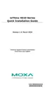
Grounding the Unit
This device has two ground pins. One pin is for system power and the other pin is for field power.
Connecting the System Power Ground
The system power ground connector is at the back of the unit. Once the device has been installed on a DIN
rail, the system power ground connector will connect to the DIN rail.