List of Figures
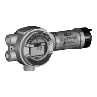
Figure 1-1. General-Purpose Ultima XA Monitor . . . . . . . . . .1-1
Figure 1-2. -Proof Ultima XE Monitor . . . . . . . . . . . . . . . . . . .1-2
Figure 1-3. Explosion-Proof Ultima XIR Monitor . . . . . . . . . . .1-2
Figure 1-4. General-Purpose XA Remote Sensor Module . . .1-3
Figure 1-5. Explosion-Proof XE Remote Sensor Module . . . .1-3
Figure 1-6. Explosion-Proof XIR Remote Sensor Module . . .1-4
Figure 1-7. Ultima XE and XIR Mounting Bracket . . . . . . . . .1-7
Figure 1-8. Ultima XIR . . . . . . . . . . . . . . . . . . . . . . . . . . . . . . .1-8
Figure 1-9. Ultima XE Grounding Terminals . . . . . . . . . . . . . .1-9
Figure 1-10. General-Purpose Two-Wire Operation . . . . . . .1-14
Figure 1-11. Explosion-Proof Two-Wire Operation . . . . . . . .1-14
Figure 1-12. General-Purpose Three-Wire Operation . . . . . .1-15
Figure 1-13. Explosion-Proof Three-Wire Operation . . . . . . .1-15
Figure 1-14. Two-Wire Printed Circuit Board
(no HART Protocol) . . . . . . . . . . . . . . . . . . . . . .1-16
Figure 1-15. Two-Wire Printed Circuit Board
(with HART Protocol) . . . . . . . . . . . . . . . . . . . . .1-17
Figure 1-16. Three-Wire Printed Circuit Board
(no HART Protocol) . . . . . . . . . . . . . . . . . . . . . .1-18
Figure 1-17. Three-Wire Printed Circuit Board
(with HART Protocol) . . . . . . . . . . . . . . . . . . . . .1-19
Figure 1-18. Remote Module General-Purpose
Ultima X Series Wiring . . . . . . . . . . . . . . . . . . . .1-20
Figure 1-19. Remote Module Explosion-Proof
Ultima X Series Wiring . . . . . . . . . . . . . . . . . . . .1-20
Figure 2-1. LCD Gas Concentration Display . . . . . . . . . . . . . .2-1
Figure 2-2. Ultima Calibrator . . . . . . . . . . . . . . . . . . . . . . . . . .2-5
Figure 2-3. Ultima Controller . . . . . . . . . . . . . . . . . . . . . . . . . .2-5
Figure 2-4. Ultima X Optional Push-button Calibrator . . . . . . .2-5
Figure 2-5. Apply ZERO Gas Flag . . . . . . . . . . . . . . . . . . . .2-14
Figure 2-6. Apply SPAN Gas Flag . . . . . . . . . . . . . . . . . . . . .2-15
Figure 2-7. Calibration End Display . . . . . . . . . . . . . . . . . . .2-17
Figure 4-1. "Change Sensor" Scrolls Across the Display . . . .4-6
Figure 4-2. Sensor Assembly and Sensor Guard
for General-Purpose Model . . . . . . . . . . . . . . . . .4-7
Figure A-1. Relay Contacts . . . . . . . . . . . . . . . . . . . . . . . . . . .A-4
Figure A-2. Relay Printed Circuit Board . . . . . . . . . . . . . . . . .A-6
Figure D-1. Zero cal step screen . . . . . . . . . . . . . . . . . . . . .D-41
viii

 Loading...