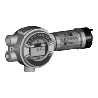
Table 1-3. Installation Outline Drawings
for Ultima X Power Supplies
MODEL POWER POWER SUPPLY POWER INSTALLATION OUTLINE
SUPPLY OUTPUT VOLTAGE SPECIFICATION DRAWING NUMBER
XA External 12 VDC 1.25 Amps, 15 W 10000020129
External 24 VDC 0.46 Amps, 11 W 10000020127
Internal 12 or 24 VDC see above SK3015-1027
XE External 12 VDC 1.25 Amps, 15 W 10000020130
External 24 VDC 0.46 Amps, 11 W 10000020128
Internal 12 or 24 VDC see above SK3015-1025 (XE) or
SK3015-1026 (XIR)
Use of External Controllers
The Ultima X Series Gas Monitors may be connected to any device
capable of accepting 4-20 mA analog signals, such as:
• Suprema Controller
• Model 9010/9020 Controller
• GasGard family controllers
• Quad Gas Controller
• Programmable Controllers
• DCS’s, etc.
When using any of the the Ultima X Series accessories (such
as relays) with the 4 to 20 mA output Ultima X Series Gas
Monitor, a three-wire connection must be used. Failure to
use a three-wire connection could damage the electronics
within the Ultima X Series Gas Monitor which can result in
serious personal injury or loss of life.
Be sure to install your Ultima X Series Gas Monitor accord-
ing to National Electrical and local procedural codes. Failure
to do so can result in an unsafe condition.
"
WARNING
1-12

 Loading...