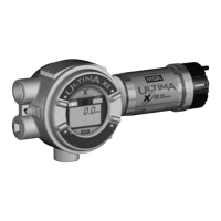
Host Interface
Analog Output
The three-wire 4-20 mA current loop is connected on terminals marked
8-30 VDC(1), 4-20 mA OUT(2), and GND (3-wire)(3). The two-wire 4-20
mA current loop is connected on the 8-30 VDC(1) and 4-20 mA OUT(2)
terminals. Refer to the installation outline drawings shown in Chapter 1,
TABLE 1-1 for details.
This is the main output from this transmitter, representing the process
gas measurement, linearized and scaled according to the configured
instrument range. This output corresponds to the Primary Variable (PV).
HART communications are supported on this loop. This device has a
Capacitance Number (CN) of 1.
An inoperative device can be indicated by down-scale or up-scale
current, depending on the sensor type. Current values are shown in
TABLE D-2.
Table D-2. Current Values
DIRECTION VALUES VALUES
(% OF RANGE) (MA OR V)
Linear over-range Down 0% 4.00 mA
Up +105.0% +1.0% 20.64 to 20.96 mA
Device malfunction
indication Down: less than 3.5 mA
Up: greater than 20.96 mA
Maximum current 22.0 mA
Multi-drop Current draw 3.5 mA
Lift-off voltage,
3-wire PCBA 8 VDC
Lift-off voltage,
2-wire PCBA 13 VDC @ 250 Ohms
D-2

 Loading...