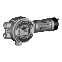
Table D-3. Device Variables Exposed by the Ultima Monitor
VARIABLE DESCRIPTION VARIABLE DESCRIPTION
Gas Type Sensor gas type description Last Cal Date Date sensor was
last calibrated
Alarm Gas value at which an Auto Zero comp Amount of compensated
Setpoints alarm status bit is set below zero drift
Alarm Action increasing or decreasing Alert option status See next section
alarm type, latching or
non latching
Alarm Status Indication of alarm setpoint Swap Delay status See next section
exceeded
Input Voltage Device input voltage level
Min/Max/Avg Minimum, maximum and Sensor Temp
avg. value of PV over time
Avg Interval Time interval for min, max, Sensor Status Status returned by
avg (1,8 or 24 hr) sensor
Gas Table Linerization table selection Relay EN/De-eng Relay EN/De-eng
RTC Date Device real time clock date Cal Sig Cal Signal Status
RTC Min Device real time clock minutes
RTC Hrs Device real time clock hours
Table D-4. Dynamic Variable implemented by Ultima Monitor
MEANING UNITS
PV Gas Value %, %LEL, PPM
Status Information
Device Status
Bit 4 ("More Status Available") is set when any failure is detected.
Command #48 gives further details.
Extended Device Status
The Ultima Monitor can predict when certain maintenance will be
required. This bit is set if a sensor fault or maintenance warning is
detected. "Device Variable Alert" is set if the PV is out of limit.
D-3

 Loading...