A-2
NOTE: To avoid electrical noise problems, do not run AC lines from
relays in the same conduit or cable tray as the DC Signal lines.
See Ultima Controller and Calibrator Manual (P/N 813379) for complete
relay configuration information.
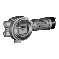
Power cable wiring lengths for the Ultima X Series Gas Monitor with
internal relays differ from models without internal relays (TABLE A-1).
Table A-1. Cable Length and Wire Size for Units
With Internal Relays
GAS SENSOR DC WIRE MAXIMUM MAXIMUM
TYPE OUTPUT VOLTAGE SIZE CABLE LENGTH LOAD
SUPPLY (AWG) WITHOUT HART RESISTANCE
(FEET) (METERS) (OHMS)
Oxygen
or Toxic 3 Wire 12 VDC 16 2,500 762 250
24 VDC 16 8,000 2,438 500
Combustible 3 Wire 12 VDC 16 900 274 250
24 VDC 16 3,000 914 500
XIR 3 wire 12 VDC 16 400 152 250
24 VDC 16 2,500 762 500
• In all installations, twisted instrument-quality cable is
recommended.
• Shielded cable is recommended in situations where radio
frequency interference (RFI), electro-magnetic interference (EMI)
or other electrical noise sources exist or are anticipated.
Ultima X Series Gas Monitor Internal Relays
Relay Specifications
Table A-2. Relay Specifications
TEMPERATURE -40 to +60°C (-40 to +140°F)
RANGE
HUMIDITY 15 to 95% RH, non-condensing
RELAYS 3 ALARMS SPDT FAULT (Single pole, double throw)
(NORMALLY-ENERGIZED) SPDT (Single pole, double throw)
RELAY At 125 or 250 VOLTS AC, 5.0 Amps or 5 Amps @ 1/10 Hp
RATINGS NON-INDUCTIVE
At 30 Volts DC, 5.0 Amps or 5 Amps @ 1/10 Hp
NON-INDUCTIVE

 Loading...