A-4
Fault Relay or Trouble
• It is a normally-energized, single-pole, double-throw (SPDT) relay.
• During normal operation, the relay contacts are normally closed
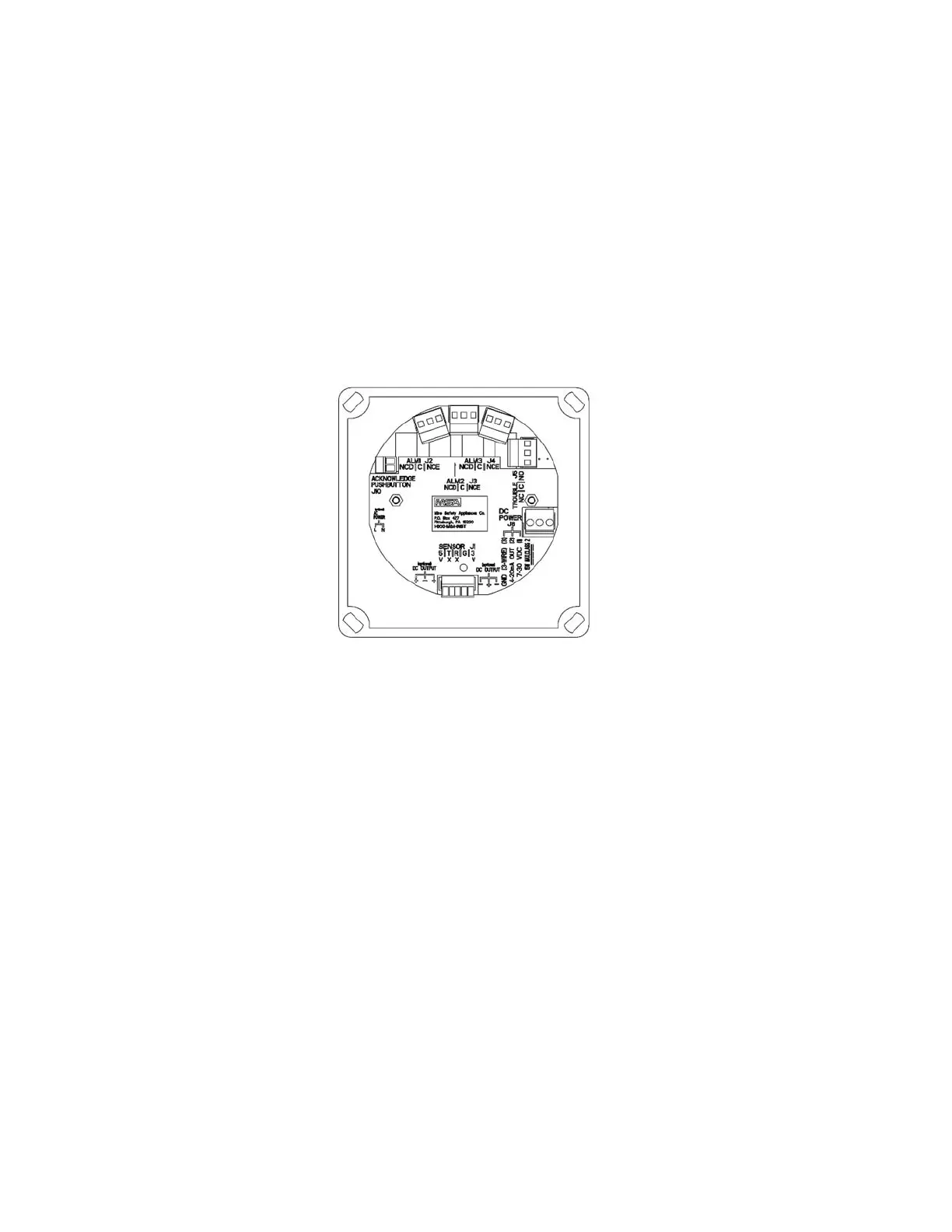
(NC) and normally open (NO) as shown in FIGURE A-1.
NOTE: FIGURE A-1 depicts the version of the printed circuit board
assembly without HART components. FIGURE 1-17 is the
equivalent HART version.
• When a fault is detected or power is cut or turned OFF, these
contacts change as follows:
• normally-closed contacts open
• normally-open contacts close.
• Provides an electrical path for fail-safe relay operation.
In the event of any failure, including power loss, the relay will
change to a fault condition.
The Fault Relay can remain STEADY ON or PULSED. These two
different modes can communicate different information to any PLC or
DCS connected to the fault relay:
• Fault Relay STEADY ON indicates:
• Ultima X Series sensor is not connected properly or
• Ultima X Series Gas Monitor internal fault or
• An inoperative relay.
Figure A-1. Relay Contacts

 Loading...


