W415-2034 / A / 10.18.19
EN
28
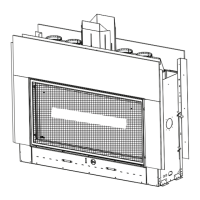
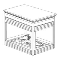
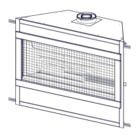
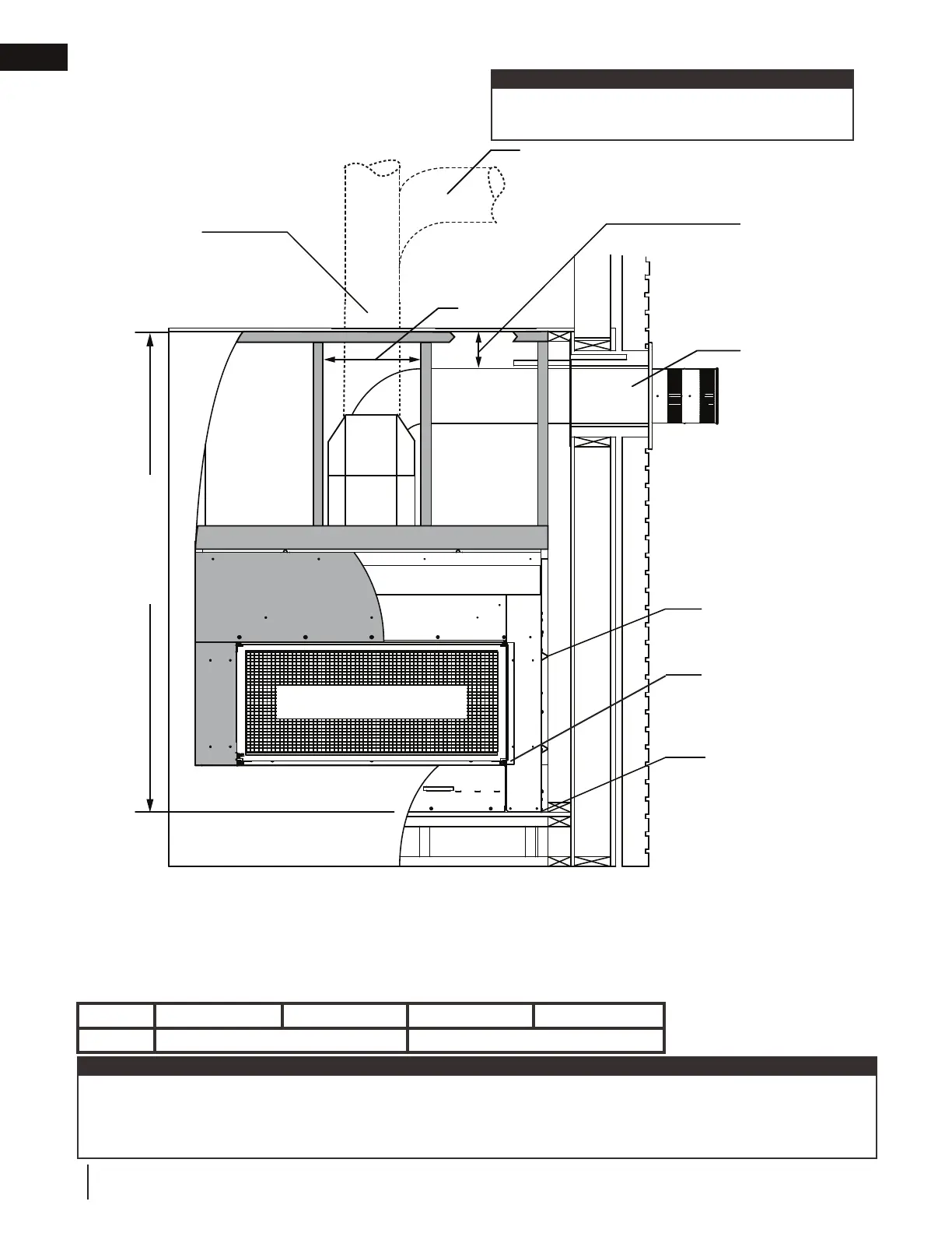
rough framing - before appliance installation
see-thru
Shaded components (fi nish framing) must be
non-combustible materials.
note:
SAFETY BARRIER
1/2” fi nishing fl ange
(4 sides)
3” [76mm] top (out-
side of enclosure)
2” [51mm] sides /
bottom (outside of
enclosure)
0” to non-
combustible fi nishing
such as brick and
stone
6” [152mm]
minimum
(inside enclosure)
0” to side standoffs
0” to base of the
appliance
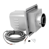
When passing
through a
ceiling, use
fi restop spacer
W500-0028 (not
supplied)
When passing
through a wall, use
fi restop spacer
W615-0162 (sup-
plied with W010-
4178 fi restop spacer
assembly)
L
Ref LV38-1 LV50-2 LV62 LV74
L
73” (185.4cm) 91” (231.1cm)
minimum clearance
The LV series requires a minimum enclosure/ceiling height, as illustrated (dimension L), measured from the bottom of
the appliance. For temperature requirements, this area must be left unobstructed. Some venting confi gurations that
require more vertical rise will require a larger enclosure to provide minimum vertical clearance between vent pipes and
combustibles.
note:
1” [25mm] minimum
all sides for sections
of vertical venting.
3” [76mm] (minimum all sides
for sections of horizontal vent-
ing) outside of enclosure.
Horizontal vent sections: A minimum clearance of 3” (76mm) on the top outside of the enclosure and 2” (51mm) on
the sides and bottom outside of the enclosure all around the vent pipe on all horizontal runs to combustibles is required.
Horizontal vent sections within enclosures require a minimum clearance of 6” (152mm) at the top of the vent pipe.
Vertical vent sections: A minimum of 1” (25mm) all around the vent pipe on all vertical runs to combustibles is re-
quired except for clearances in appliances enclosures. Vertical vent sections within enclosures require a minimum clear-
ance of 1” (25mm) around the vent pipe.
14”
(35.6cm)
min.
 Loading...