 Loading...
Do you have a question about the Napoleon Vector Series and is the answer not in the manual?
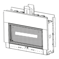
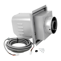
| Vent Type | Direct Vent |
|---|---|
| Burner Material | Stainless Steel |
| Weight | Varies by model |
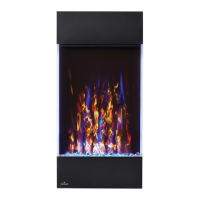
| Model | Vector Series |
| Fuel Type | Natural Gas or Propane |
| Viewing Area | Varies by model |
| Glass Type | Ceramic |
| Ignition System | Electronic Ignition |
| Dimensions | Varies by model |
| Warranty | Limited Lifetime Warranty |
| Remote Control | Standard (eFIRE remote) |