VRA53801 - R.3609.A
- A
3・
LS-50 -
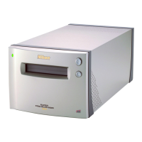
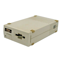
4. Scan motor unit
・Attach the harness of the scan motor unit (1) on the mechanical base unit (1) so that ( 〇 ) part of the
harness is positioned at the left side.
・Fix the scan motor unit (2) with 2 screws (3).
・Hook the harness of the scan motor unit (2) to the claws of the backside of the mechanical base unit (1) at
the above 4 positions as shown by ( 〇 ) and pinch one part of the harness at the above ( 〇 )
position.
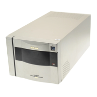
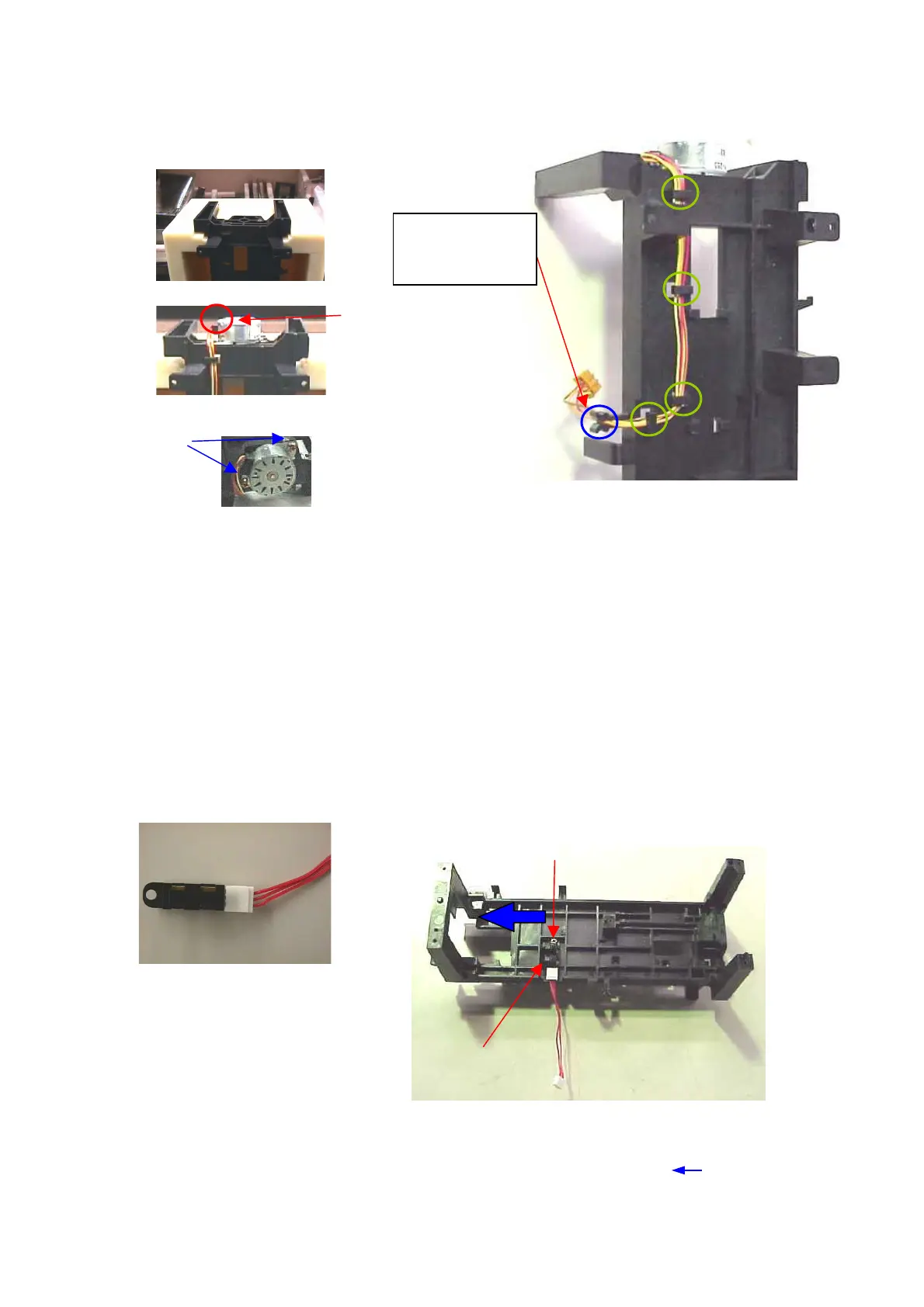
5. Photo interrupter
・Connect the photo interrupter harness (2) to the photo interrupter (1).
・Attach the photo interrupter (1) on the mechanical base unit (3).
・Fix the photo interrupter (1) with the screw (4) by pressing it in the direction of ( ).
③
②
①
②
①
Twist once and
put here to be
pinched in.
③
①
④
①
②