VRA53801-R.3609.A
- M6 ・ -
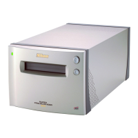
LS-50
2 Specications by function
2.1 Adjust light exposure
The light exposure is adjusted by changing the exposure time and gain.
・Exposure time: controlled by the blinking time of the LED. The blinking time is controlled by
the MCU’s setting of the count value for the custom IC timer.
・Gain The controllable gain by the analog hardware has 2 levels: 1.00-fold and 2.00-fold of
magnication (typ).
In case the exposure time is 64 times or under as long as the white balancing time, only the exposure
time is increased/decreased.
In case the above time exceeds 64 times, the gain is switched to 2.00-fold of magnication.
But regarding "I-ch”, the gain is always switched to 2.00-fold of magnication when scanning.
2.2 Dark voltage correction
The dark signal voltage (VDRK) is corrected by adding offset to the CCD signal, using D/A.
The dark signal non-uniformity (DSNU) is corrected digitally per pixel by the custom IC.
Whenever the driver software gives instructions, or the scanner is initialized, or commands are
operated for CCD's scanning, the correction coefcient is measured.
The dark voltage corrections are made for each color and line.
2.3 Shading correction
The illumination irregularity and the CCD non-uniform sensitivity is corrected digitally per pixel by
16-bit correction coefcient of each color.
The correctable irregularity/non-uniformity is 49.98% or under.
In case the irregularity/non-uniformity before the correction exceeds 49.98%, errors occur.
The correct coefcient, of which characteristic is reverse against the uncorrected shading input, is
calculated.
Whenever the driver software gives instruction or the scanner is initialized or the adapter is replaced,
the correction coefcient is measured.
2.4 White balance
With the shading corrected, the exposure time is adjusted so that the average value of each color (R,
G, B, and I) falls in the range of 90% of the full-scale value.
Whenever the driver software gives instructions or the scanner is initialized or the lm is pulled out
or the adapter is replaced, the correction coefcient is measured.
2.5 Averaging
The averaging in the main scanning direction is possible by the custom IC in the scanner.
Scanning pitch 1, 2:2 pixel average
pitch 3 :4 pixel average (No odd-number pitch for [S0010])
pitch 4 - :8 pixel average
The averaging is used when pre-scanning, or thumbnail-scanning by IA-20(S) and SA-21, or main
scanning with pitch 2 (for resizing process).