VRA53801 - R.3609.A
- A
19 ・
LS-50 -
③
④
①
①
③
②
⑤
①
②
③
④
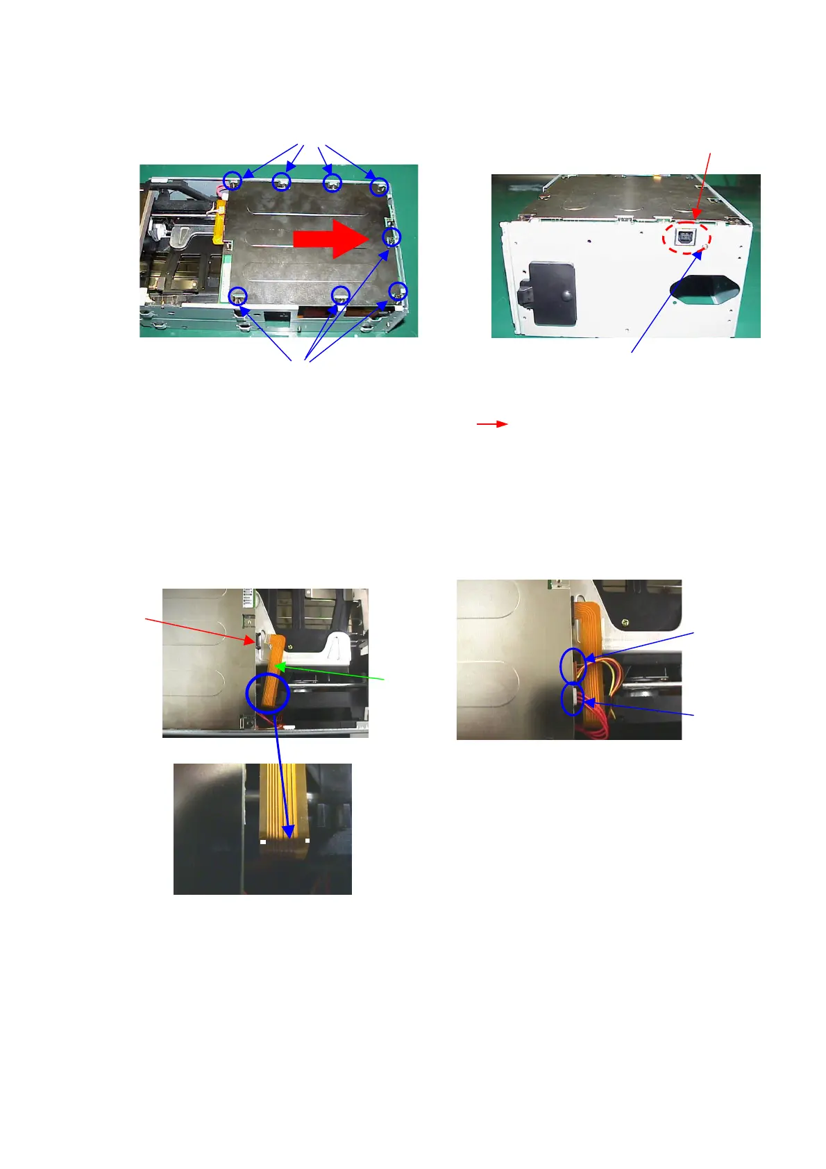
25-3. Attach Main PCB
・Attach the main PCB unit (2) on the mechanical base unit (1).
・Put the main PCB unit (2) by pressing it in the direction of ( ), and fix it with 8 screws (3).
・Fix the connector shield plate A (5) with the screw (4).
26. Attach AF-FPC / Scan motor harness
・Fold the AF-FPC (1) along the folding marks as shown by ( 〇 ).
・Connect the AF-FPC (1) to the connector of the main PCB unit (2).
・Connect the harness (4 lines) of the scan motor unit (3) and the harness (3 lines) of the photo interrupter
(4) to the main PCB unit (2).