VRA53801-R.3609.A
- M5 ・ -
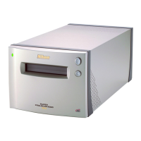
LS-50
・Illumination LED driving unit:
This consists of the transistor array, regulators, and resistors, etc. Turning ON/OFF of the
transistor controls LED lighting of R, G, B, and I.
・Motor unit:
This is equipped with 2 motor driving circuits for the body, and 2 motor driving circuits for the
adapters.
Body unit stepping motor × 2 circuits
Adapter stepping motor × 1 circuit
5V-series DC motor × 1 circuit
1.4 CCD-PCB (CCD unit)
This consists of PCB, CCD, CCD installing-plate, and CCD insulating sheet.
The scanner uses CCD with 3964 effective pixels in the form of the monochrome linear sensor.
The output signals from CCD are, via the emitter follower (buffer), output to the main PCB. The
CCD-PCB is connected to the main PCB by the CCD-FPC.
1.5 Power-supply unit
This uses plastic boards, and includes the power-supply circuit, AC inlets, and power-supply switch.
While the input voltage ranges from AC85 to 264V, the output voltage is 5V, -12.2V, and +15.5V.
1.6 Connect adapter and feeder to the body
・Mechanical connections
The adapter rails are engaged in the grooves of the AD installing plate on the body side. The
adapter is pushed from above to the AD-installing plate by the spring. When the adapter is
inserted, the convexity part of the spring enters in the concavity part of the adapter.
・Electric connections
Via connector connection. The connection can be made when the power of the body is ON (hot
plug supported).
But MA-21 has no connector, so cannot be connected electrically.
・Connection identication
Via the detection switch.
Whether connected or not depends on signals of the connection-connectors. (The adapter has a
circuit checking signals and identies connections; MA-21 has no circuit.)
In case out-of-support adapter (SA-20) is inserted, errors blink on the LED.