Basic System Configuration Guide System Management
Edition: 01 3HE 11010 AAAC TQZZA 237
During startup, the PTP slave clock receives the synchronization messages from the
PTP master clock before a network delay calculation is made. Prior to any delay
calculation, the delay is assumed to be zero. A drift compensation is activated after
a number of synchronization message intervals occur. The expected interval
between the reception of synchronization messages is user-configurable.
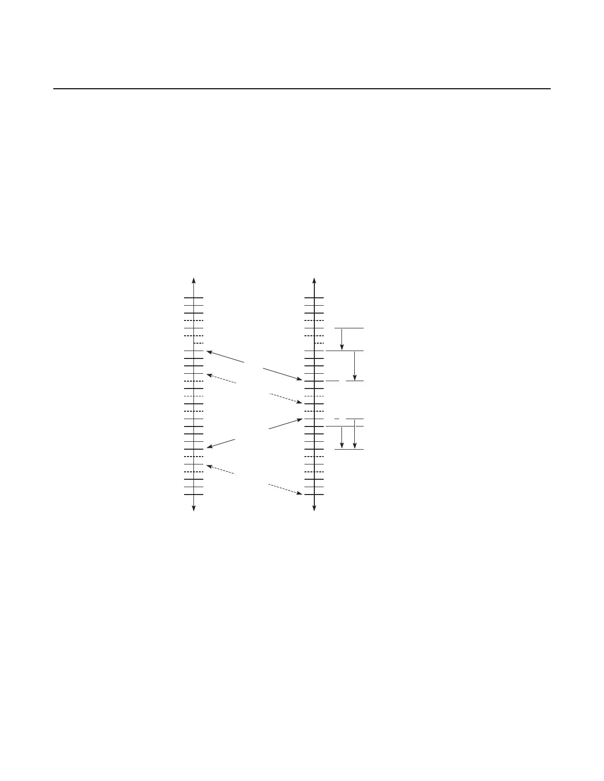
The basic synchronization timing computation between the PTP slave clock and PTP
best master is illustrated in Figure 15. This figure illustrates the offset of the slave
clock referenced to the best master signal during startup.
Figure 15 PTP Slave Clock and Master Clock Synchronization Timing
Computation
6.4.6.2 Performance Considerations
Although IEEE 1588v2 can be used on a network that is not PTP-aware, the use of
PTP-aware network elements (boundary clocks) within the packet switched network
improves synchronization performance by reducing the impact of PDV between the
grand master clock and the slave clock.
Slave
t1, t2, t3, t4 are measured values
t2 - t1 = Delay + Offset = 51 - 44 = 7
t4 - t3 = Delay - Offset = 57 - 56 = 1
Delay = ((t2-t1) + (t4 - t3))/2 = 4
Offset = ((t2 - t1) - (t4 - t3))/2 = 3
O = Offset = Slave - Master
OD
40
D = Delay
20503
42
44
46
48
50
52
54
56
58
60
62
64
Master
40
42
44t1
38
46
48
50
52
54
56
58
t4
60
62
t3
t2
Sync
Follow_up (t1)
Delay_req
Delay_resp (t4)
 Loading...