System Management
242
Basic System Configuration Guide
3HE 11010 AAAC TQZZA Edition: 01
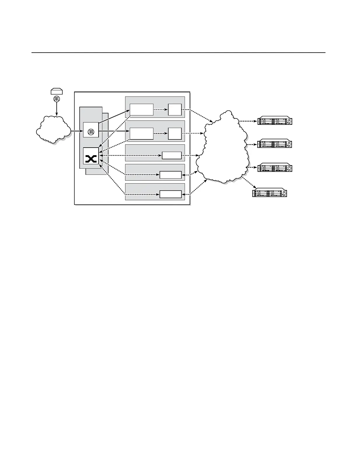
Figure 19 Ordinary Master Clock Operation
Each PTP master clock is configured for a specific slot where the card (see Table 26)
or Ethernet port (see Table 25) will perform the master function. On the 7705 SAR-M,
7705 SAR-H, 7705 SAR-Hc, 7705 SAR-A, 7705 SAR-Ax, 7705 SAR-W, and
7705 SAR-Wx, this slot is always 1/1. On the 7705 SAR-X, this slot is always either
1/2 or 1/3. When the 7705 SAR-M is receiving PTP packets on a 2-port 10GigE
(Ethernet) module, its PTP clock continues to use slot 1/1. Each master is also
associated with an IP interface on a specific port, adapter card, or loopback address
for the router; however, the IP interface configured on a 2-port 10GigE (Ethernet)
module cannot be associated with a master clock. All packets that ingress or egress
through a port where the master is configured are routed to their destination via the
best route as determined in the route table.
Each master clock can peer with up to 50 slaves or boundary clocks. The IP
addresses of these peers can be statically configured via CLI or dynamically
accepted via PTP signaling messages. A statically configured peer may displace a
dynamic peer on a particular PTP port. If there are fewer than 50 peers, then that
dynamic peer can signal back and be granted a different PTP-port instance.
CSM B
21311
Ethernet
Ethernet
Ethernet
OC3/STM1
T1/E1/DS3/E3
CSM A
Packet
Network
PTP Master
Clock
Switch
PTP Master
Clock
SSU
PTP Slave
PTP Slave
PTP Slave
PTP Slave
PRC
TDM/SyncE
Network
Timing
Reference
Eth
Port
Eth
Port
Eth Port
POS Port
PPP Port
 Loading...