Page 64 of 206 Installation
553-3001-304 Standard 3.00 September 2004
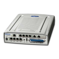
• Link LEDs
— LNKOK – lit when there is a network connection
— ACT – lit when there is system activity
— COL – lit if there are network collisions
• NETWORK – connects the WLAN IP Telephony Manager 2245 to the
wired Ethernet LAN
• ERROR LED – lit when the system has detected an error
• Status LEDs – indicate system error messages and status
— 1 – heartbeat
— 2 – active calls
— 3, 4, 5 – currently unused
• PWR – connects to the AC adapter supplying power to the system
Wall mounting
The WLAN IP Telephony Manager 2245 can be mounted either vertically or
horizontally.
Procedure 1
Mounting the WLAN IP Telephony Manager 2245 to the wall
1 Use a 1/8-inch drill bit to drill four pilot holes, on 1.84 by 12.1 inch centers
(approximately equivalent to 1-13/16 inch by 12-1/8 inch).
2 Insert the #8 x 3/4-inch screws in the pilot holes and tighten, leaving a
1/8 to 1/4-inch gap from the wall.
3 Slide the WLAN IP Telephony Manager 2245 over the screws until the
WLAN IP Telephony Manager 2245 drops into place in the keyhole
openings of the flange.
WARNING
Use only the provided Class II AC adapter with 24V DC,
1A output.