Page 66 of 206 Installation
553-3001-304 Standard 3.00 September 2004
Connecting to the power
Follow the steps in Procedure 3 to connect the power to the WLAN IP
Telephony Manager 2245.
Procedure 3
Connecting the power
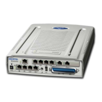
1 Connect the power plug from the AC adapter to the jack labeled PWR on
the WLAN IP Telephony Manager 2245.
2 Plug the AC adapter into a 110V AC outlet to supply power to the WLAN
IP Telephony Manager 2245.
The system cycles through diagnostic testing and the LEDs blink for
approximately one minute.
3 When the system is ready for use, verify the following:
a. The ERROR LED is off.
b. Status 1 is blinking.
End of Procedure
Installing the WLAN Application Gateway 2246
For information on installing the optional WLAN Application Gateway 2246,
refer to Appendix A: “WLAN Application Gateway 2246” on page 155.
WARNING
Use only the provided Class II AC adapter with output
24V DC, 1A.