General Routing Guidelines
NVIDIA Jetson Xavier NX DG-09693-001_v1.7 | 89
18.5 Common High-Speed Interface
Requirements
The following table describes the common high-speed interface requirements.
Table 18-2. Common High-Speed Interface Requirements
Parameter Requirement Units Notes
Common-mode Choke (Not recommended – only used if absolutely required for EMI issues)
Preferred device Type: TDK ACM2012D-900-2P. Only if
needed. Place near connector. Refer to
Common Mode Choke Requirement
section.
Location - Max distance from to adjacent
discontinuities – ex, connector, AC cap)
8 (53) mm (ps) TDK ACM2012D-900-2P
See Figure 18-2
@T
R-200ps (10%-90%)
Common-mode impedance @ 100MHz Min/Max 65/90 Ω
Max Rdc 0.3 Ω
Differential TDR impedance 90 Ω
Min Sdd21 @ 2.5GHz 2.22 dB
Max Scc21 @ 2.5GHz 19.2 dB
Serpentine
Min bend angle 135 deg (α) S1 must be taken care to consider Xtalk
to adjacent pair. See USB 3.2 Guideline
in Figure 18-3.
Dimension Min A Spacing
Min B, C Length
Min Jog Width
4x
1.5x
3x
Trace width
General
Routing over Voids Routing over voids not allowed except void around device ball/pin the signal
is routed to.
Noise Coupling Keep critical high-speed traces away from other signal traces or unrelated
power traces/areas or power supply components
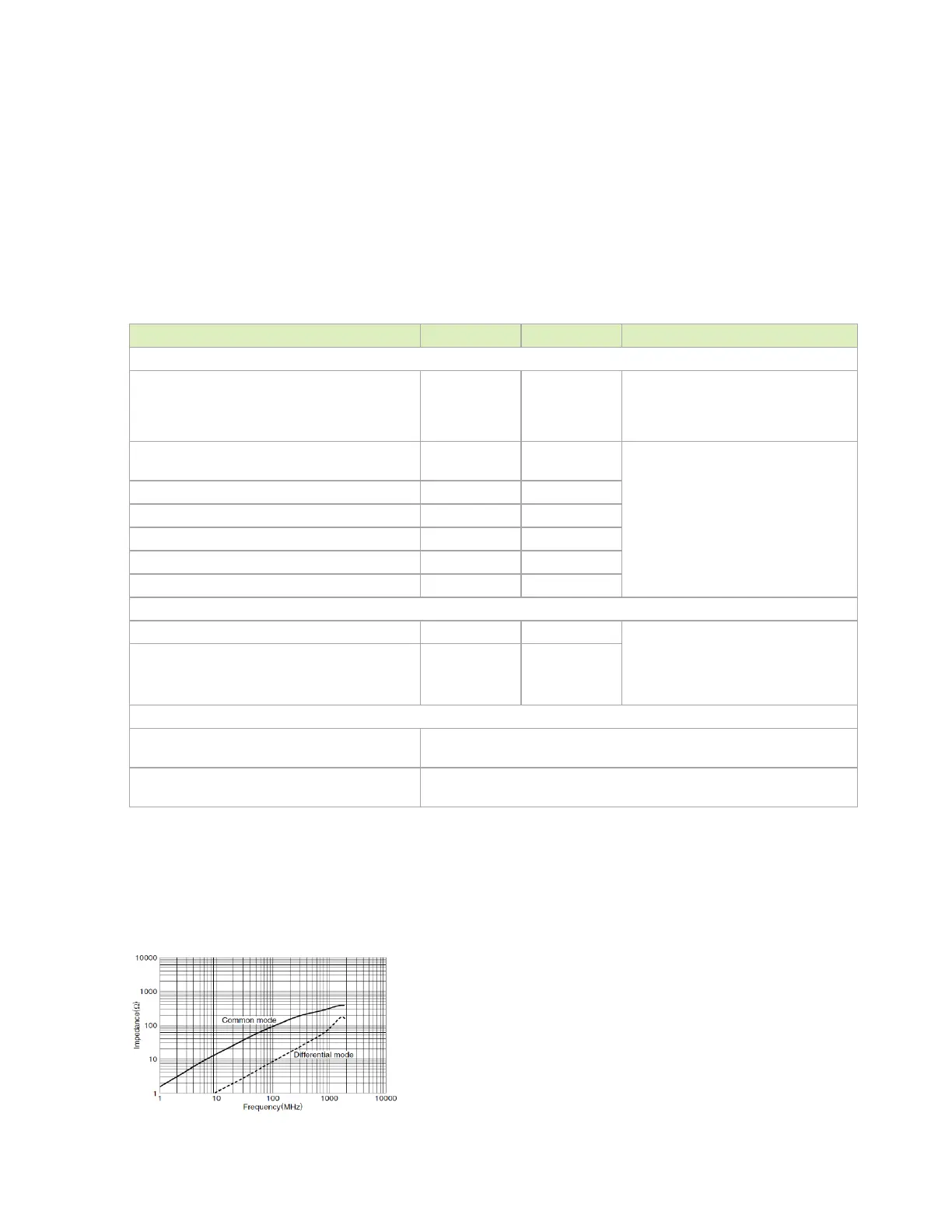
The following figures show the common high-speed interface signal routing requirements.
Figure 18-2. Common Mode Choke

 Loading...


