134
CPU Bus Unit Setting Area Capacity Section 2-7
Note The current consumption is 0.15 A per Unit when using the NT-AL001 RS-
232C/RS-422A Converter and 0.04 A per Unit when using the CJ1W-CIF11
RS-422A Converter.
CJ-series
Communications
Adapters
Current Consumptions for 24-V Supply
2-7 CPU Bus Unit Setting Area Capacity
Settings for most CPU Bus Units are stored in the CPU Bus Unit Setting Area
in the CPU Unit. Refer to 9-22 Parameter Areas for details. The CPU Bus
Units are allocated the required number of works for settings from this area.
There is a limit to the capacity of the CPU Bus Unit Setting Area of 10,752
bytes (10 Kbytes). The system must be designed so that the number of words
used in the CPU Bus Unit Setting Area by all of the CPU Bus Units not exceed
this capacity. If the wrong combination of Units is used, the capacity will be
exceeded and either Units will operate from default settings only or will not
operate at all.
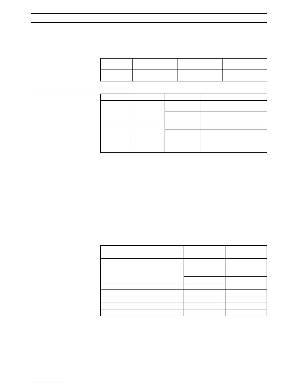
The following table shows the number of bytes required in the CPU Bus Unit
Setting Area by each Unit. Any Unit with a usage of “0” does not use the CPU
Bus Unit Setting Area at all.
Category Name Model Current consump-
tion (A)
Communica-
tions Adapters
RS-422A Converter CJ1W-CIF11 0.04
Category Name Model Current consumption (A)
Basic Output
Units
Relay Contact
Output Units
CJ1W-OC201 0.048
(0.006 x number of ON points)
CJ1W-OC211 0.096
(0.006 x number of ON points)
Special I/O
Units
ID Sensor Units CJ1W-V600C11 0.12
CJ1W-V600C12 0.24
Advanced
Motion Control
Unit
CJ1W-MCH71 0.3
Name Model number Capacity in bytes
Controller Link Unit CJ1W-CLK21-V1 512
Serial Communications Unit CJ1W-SCU21/31/
41-V1
0
Ethernet Unit CJ1W-ETN11 412
CJ1W-ETN21 994
FL-net Unit CJ1W-FLN21 998
DeviceNet Unit CJ1W-DRM21 0
Position Control Unit CJ1W-NCF71 0
Motion Control Unit CJ1W-MCH71 0
Storage and Processing Unit CJ1W-SPU01 0
 Loading...


