440
Parameter Areas Section 9-22
Programming Device’s Operation Manual for details on registering the I/O
Table s.
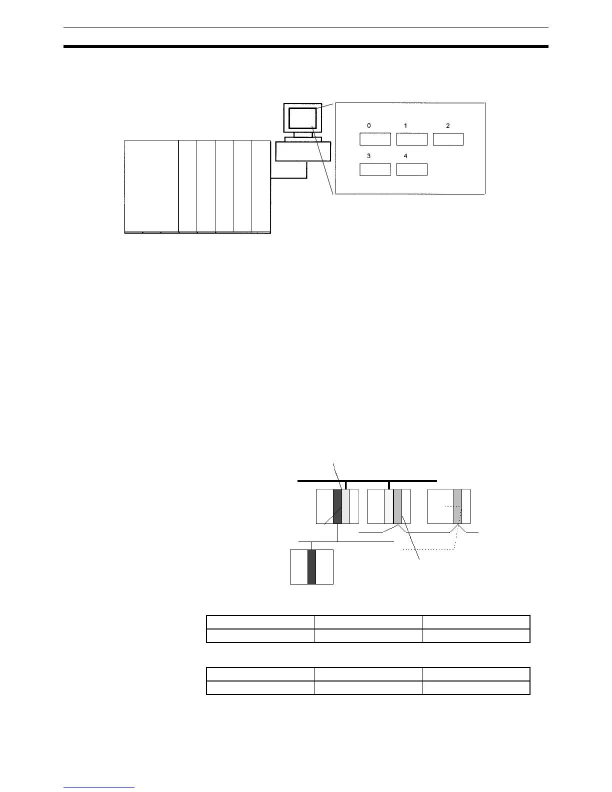
The I/O Setting Error Flag (A40110) will be turned ON if the models and loca-
tions of the Units actually mounted to the PLC (CPU Rack and Expansion
Racks) do not match the information in the Registered I/O Table.
By default, the CJ-series CPU Unit will automatically create I/O tables at star-
tup and operate according to them. I/O tables do not necessarily need to be
created by the user.
9-22-3 Routing Tables
When transferring data between networks, it is necessary to create a table in
each CPU Unit that shows the communications route from the local PLC’s
Communications Unit to the other networks. These tables of communications
routes are called “Routing Tables.”
Create the Routing Tables with a Programming Device or the Controller Link
Support Software and transfer the tables to each CPU Unit. The following dia-
gram shows the Routing Tables used for a data transfer from PLC #1 to PLC
#4.
1,2,3... 1. Relay Network Table of PLC #1:
2. Relay Network Table of PLC #2:
4
3
1
02
CPU Unit
Regis-
tered
I/O
Table
Analog
Communications
16-point Output
12-point Output
16-point Input
Programming Device
Input 16 Output 12 Output 16
Analog
Commu-
nications
Node number M
Network 2
PLC#3 PLC#2
PLC#1
Unit number n
PLC#4
Network 3
Node number N
Network 1
Destination network Relay network Relay node
31N
Destination network Relay network Relay node
32M