EasyManuals Logo

Omron CJ - 08-2008 User Manual

Omron CJ - 08-2008
733 pages
To Next Page IconTo Next Page
To Previous Page IconTo Previous Page
Page #570 background imageLoading...
Page #570 background image
522
Error Processing Section 11-2
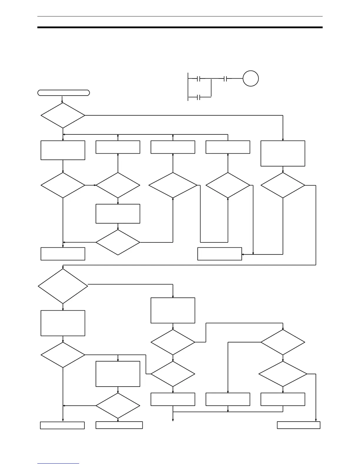
11-2-13 I/O Check
The I/O check flowchart is based on the following ladder diagram section
assuming that SOL1 does not turn ON.
NORMAL
YES
NO YES YES
NORMAL YES NORMAL
NORMAL ABNORMAL
NO
NO
YES
NO NO
ABNORMA
L
NO
YES
ABNORMAL
NORMAL
ABNORMAL
ABNORMAL
NORMAL
YES
NO
YES
ABNORMAL
NO
000500
000002
(LS1)
000003
(LS2)
SOL1
000500
Check LS1 and LS2
Replace Input Unit
Return to START
Correctly wire Tighten
Remove external
wiring and provide
dummy input signal
to check
Operation OK?
Voltage normal?
Check terminal
voltages of 000002
and 000003 with
tester
Check output de-
vice SOL1
Check terminal
voltages of 000002
and 000003 with
tester
Voltage normal?
Indicators of
inputs (000002,
000003) normal?
Voltage normal?
Replace Output
Unit
(Unit without
fuse)
Output wiring
correct?
Voltage normal?
Check terminal
voltage of 000500
with tester
Is the blown
fuse indi-
cator lit?
Replace fuse
Correct wiring
Replace terminal
block connector
Faulty terminal
block connector
contact?
START
Indicator of
000500
normal?
Disconnect external
wiring and check
terminal voltage of
000500 with tester
(Units with
internal
fuse)
Replace Input Unit
Terminal
screws loose?
Faulty
terminal block
connector
contact?
Replace terminal
block connector
Operation OK?
Monitor ON/OFF
status of 000500
with Programming
Device
Input wiring
correct?

Table of Contents

Questions and Answers:

Question and Answer IconNeed help?

Do you have a question about the Omron CJ - 08-2008 and is the answer not in the manual?

Omron CJ - 08-2008 Specifications

General IconGeneral
BrandOmron
ModelCJ - 08-2008
CategoryController
LanguageEnglish

Related product manuals