212
Examples Section 4-2
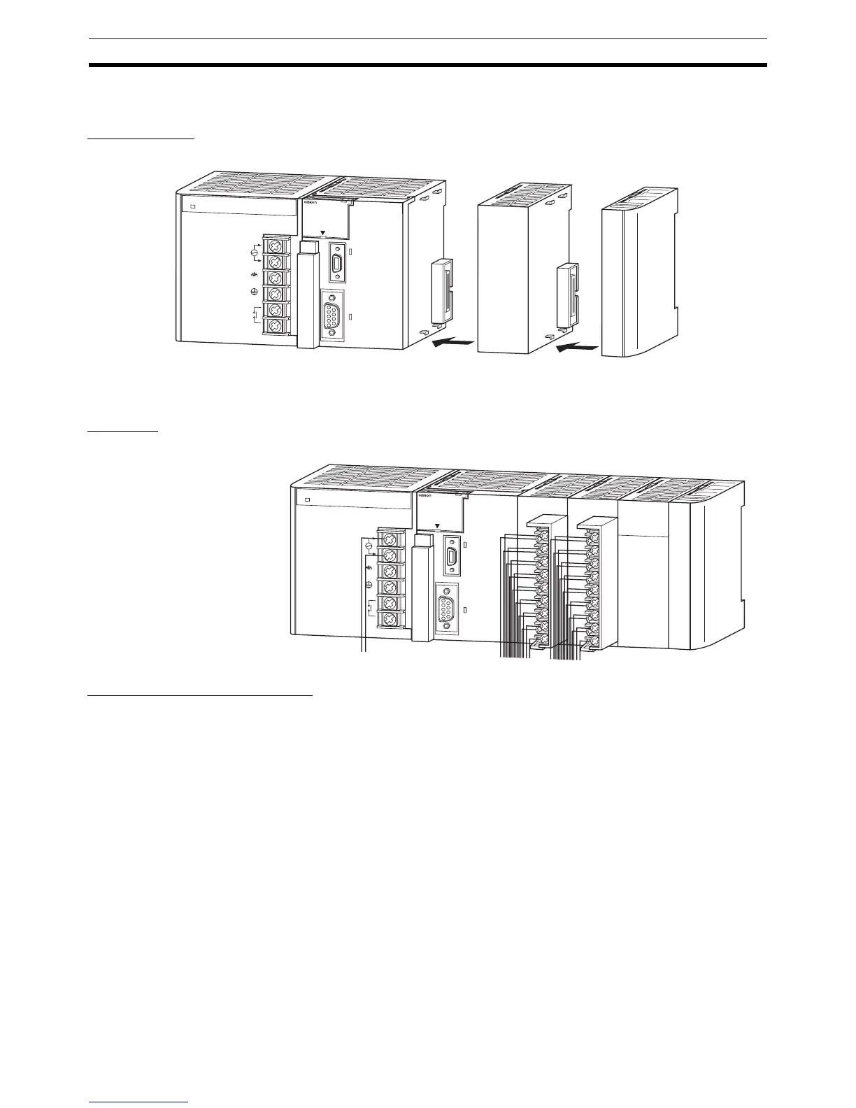
4-2 Examples
1. Installation
Connect the Units. When necessary, install a Memory Card.
Make sure that the total power consumption of the Units is less than the max-
imum capacity of the Power Supply Unit.
2. Wiring
Connect the power supply and I/O wiring.
3. Initial Settings (Hardware)
Make necessary hardware settings such as the DIP switch settings on the
CPU Unit. Be sure that the communications settings for the peripheral port
and RS-232C port are correct, especially when connecting a Programming
Device (CX-Programmer or Programming Console).
When connecting to the peripheral port, turn OFF pin 4. When connecting the
CX-Programmer to the RS-232C port, turn ON pin 5.
Note When devices other than a Programming Console and Programming Device
are connected to the peripheral port and RS-232C port, turn ON pin 4 and
turn OFF pin 5.
P
A
2
0
5
R
POWER
IN
P
U
T
A
C
1
0
0
-2
4
0
V
L2/N
L1
D
C
2
4
V
A
C
2
4
0
V
O
U
T
P
U
T
R
U
N
PERIPHE
RAL
ERR/ALM
RUN
INH
COMM
PRPHL
C
O
N
T
R
O
LLE
R
C
J
1
G
-
C
P
U
4
4
S
Y
S
M
A
C
P
R
O
G
R
A
M
M
A
B
L
E
P
O
R
T
OPEN
B
U
S
Y
M
C
P
W
R
2
ON
4
TERM
RD2
SD2
RDY
NO.
UNIT
ERH
OFF
WIRE
0
1
2
3
4
5
6
7
8
9
A
B
C
D
E
F
ERC
RUN
SCU41
RD1
TER1
SD1
PORT1
(RS422
/485)
PORT2
P
A
2
0
5
R
POWER
IN
P
U
T
A
C
1
0
0
-2
4
0
V
L2/N
L1
D
C
2
4
V
A
C
2
4
0
V
O
U
T
P
U
T
R
U
N
PERIPHE
RAL
ERR/ALM
RUN
INH
COMM
PRPHL
C
O
N
T
R
O
LLE
R
C
J
1
G
-
C
P
U
4
4
S
Y
S
M
A
C
P
R
O
G
R
A
M
M
A
B
L
E
P
O
R
T
OPEN
B
U
S
Y
M
C
P
W
R
 Loading...


