203
B7A Interface Unit Section 3-7
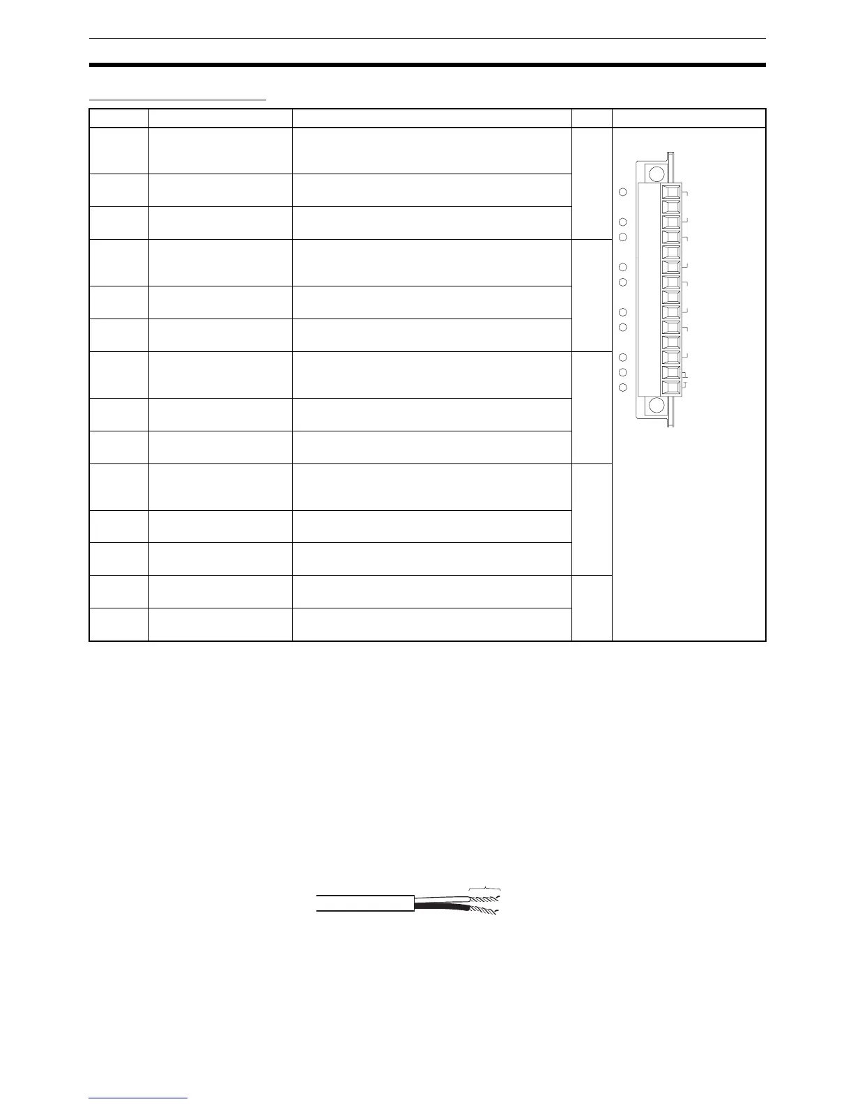
Terminal Arrangement
Note Terminals V1, V2, V3, V4, and V are connected internally in the Unit, and ter-
minals G1, G2, G3, G4, and G are connected internally in the Unit.
3-7-9 Preparing and Connecting Cables
Use the following procedure to prepare and connect the cables.
Note Always turn OFF the Unit's power supply and communications power supply
before attaching or removing connectors.
1) Preparing the Covering First, use the following procedure to prepare the cable.
1,2,3... 1. Strip approximately 10 mm of the sheath covering the signal lines to match
the crimp terminals. Next, twist together the wires of each signal line firmly.
Terminal Name Function Word Appearance
A Port 1 power supply: V1 Connect to the + terminal of the B7A Link Termi-
nal to be connected to port 1 (only when using a
common power supply).
n Connector with clamps
B Port 1 signal: SIG1 Connect to the SIG terminal of the B7A Link Ter-
minal to be connected to port 1.
C Port 1 ground: G1 Connect to the − terminal of the B7A Link Termi-
nal to be connected to port 1.
D Port 2 power supply: V2 Connect to the + terminal of the B7A Link Termi-
nal to be connected to port 2 (only when using a
common power supply).
n+1
E Port 2 signal: SIG2 Connect to the SIG terminal of the B7A Link Ter-
minal to be connected to port 2.
F Port 2 ground: G2 Connect to the − terminal of the B7A Link Termi-
nal to be connected to port 2.
G Port 3 power supply: V3 Connect to the + terminal of the B7A Link Termi-
nal to be connected to port 3 (only when using a
common power supply).
n+2
H Port 3 signal: SIG3 Connect to the SIG terminal of the B7A Link Ter-
minal to be connected to port 3.
I Port 3 ground: G3 Connect to the − terminal of the B7A Link Termi-
nal to be connected to port 3.
J Port 4 power supply: V4 Connect to the + terminal of the B7A Link Termi-
nal to be connected to port 4 (only when using a
common power supply).
n+3
K Port 4 signal: SIG4 Connect to the SIG terminal of the B7A Link Ter-
minal to be connected to port 4.
L Port 4 ground: G4 Connect to the − terminal of the B7A Link Termi-
nal to be connected to port 4.
M + power supply: V Connect to the + terminal of the external power
supply.
---
N − power supply: G Connect to the − terminal of the external power
supply.
A V1
B SIG1
C G1
D V2
E SIG2
F G2
G V3
H SIG3
I G3
J V4
K SIG4
L G4
M V
N G
SIG
SIG
SIG
SIG
+
−
+
−
+
−
+
−
+
−
IN4
IN1
IN2IN3
Approx. 10 mm
 Loading...


